
Cocos Shader Series - Blend Testing
Series Chapters
- Basic Introduction
- Build A Triangle
- Draw More Things
- Add Some Texture
- Draw Shaders With Cocos Creator
- Change a shader with a texture map
- Use a Noise Map to Make a Disolve Texture
- Building With WebGL
- Alpha Testing and Blending
- Blend Test
Blend Test
What we often call blending is a technique that deals with the transparency of an object. For example, in a real-life glass window, we can see through the transparency of the object. Transparent objects are classified as fully transparent (allowing all colors to pass through with zero transparency) and translucent (allowing colors to pass through with their own colors). Transparency is determined by the alpha value, which is the a-component of the color (RGBA). When an object has an alpha of 0.5, it means that 50% of the object’s color comes from itself and 50% from the color of the object behind it.
For most 3D objects, opaque (transparency of 1) mapping is used. They only need to decide which object is rendered in the final fragment based on depth detection. The object depth is tested against the depth in the depth buffer according to the specified comparison function, and any failed fragment is discarded. Transparent objects, however, do not make sense with a set of rules that simply use depth testing and are prone to rendering transparent objects incorrectly. So, we need to tell WebGL how to handle texture elements with alpha information (as mentioned in Chapter 4, the pixels that make up the texture image).
Transparency test
As we said in the previous section, transparent objects are divided into fully transparent and semi-transparent. If some images do not need to be translucent, they only need to show a part of them according to the texture color value or not show a part of them, without intermediate cases, like the image below.

As you can see from the figure, the top part has a transparent area. In practice, if the transparent area is not processed, the default will take the color that comes behind it as follows:

Suppose you want to solve the above display error so that the transparency information of the image is recognized. In that case, you only need to set a threshold, compare the threshold with the texture alpha value, and discard the fragments (pixels) within the threshold limit. GLSL gave us the discard command, and once it is called, it guarantees that the fragment will not be processed further.
vec4 frag () {

vec4 col = mainColor * texture(mainTexture, v_uv);

// Before this, set a uniform alphaThreshold as the threshold, which defaults to 0.1; the larger the threshold, the more pixels may be rejected

if(col.a < alphaThreshold){

discard;

}

return col;

}
Transparency blending
While discarding fragments is easy for us, we are looking to see the effect of interactions between transparent objects more often than not. It is not possible to just discard fragments, as is the case with rendering opaque and fully transparent objects, but rather it is necessary to render multiple transparency levels simultaneously, if necessary. Therefore, blending needs to be enabled (Blending). When blending is enabled, depth writing needs to be turned off. As mentioned in the previous chapter, the corresponding part is replaced when depth detection is performed, so it is an A or B operation.
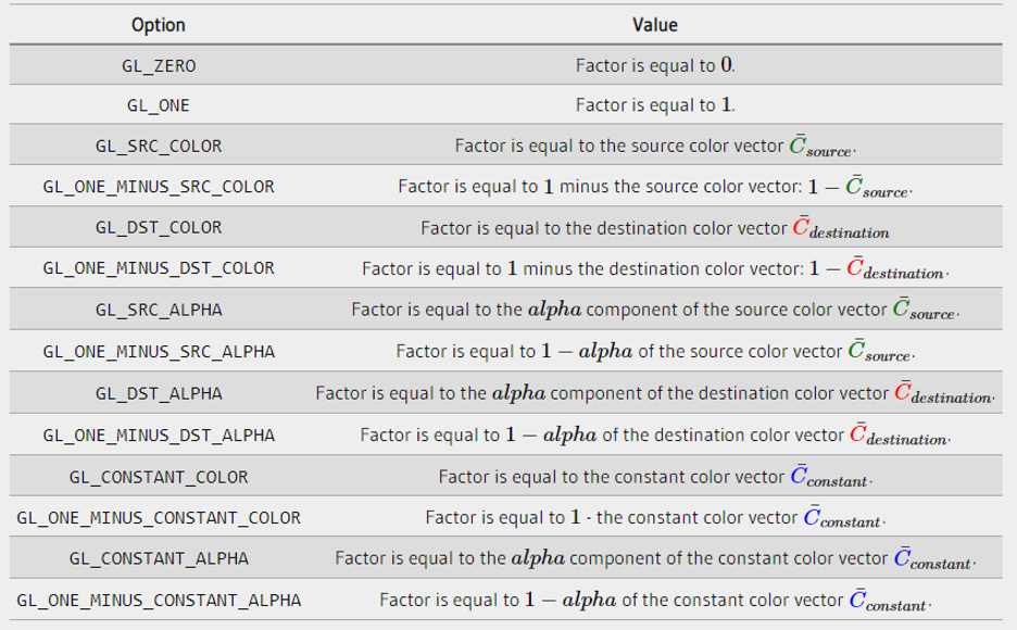
The blending approach always follows the following equation.
color(RGBA) = ((sourceColor * sfactor) + (destinationColor * dfactor)). RBGA
-
sourceColor: the source color vector. This is the color vector from the texture.
-
destinationColor: the destination color vector. This is the color vector currently stored in the color buffer.
-
sfactor: the source factor value. Specifies the effect of the alpha value on the source color.
-
dfactor: dfactor value. Specifies the effect of the alpha value on the target color.
In blending, most commonly used as the depth test, there is a blending function:
"void gl.blendFunc(GLenum sfactor, GLenum dfactor);."
-
sfactor: source blend factor. The default value is ZERO.
-
dfactor: target blend factor. The default value is ZERO.
If you need to set them separately, you can also use void gl.blendFuncSeparate(srcRGB, dstRGB, srcAlpha, dstAlpha); to set them (since each parameter name is clear enough, no additional description will be added here).
Above, all the factor values range from [0, 1], involving the constant part, which needs to be set by void gl.blendColor(red, green, blue, alpha); and each component value also ranges from [0, 1].
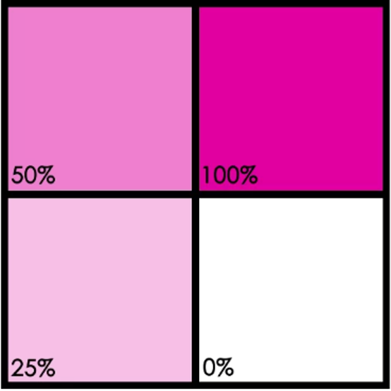
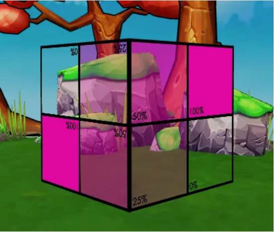
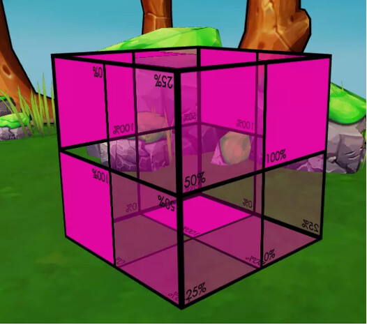
Next, try to practice this in Cocos Creator 3.x. Import an image with transparency. The image I used here is as follows, with the transparency of each grid of the image marked in the bottom left corner of the image.
Next, the image import is applied to both face slices and looks like this:
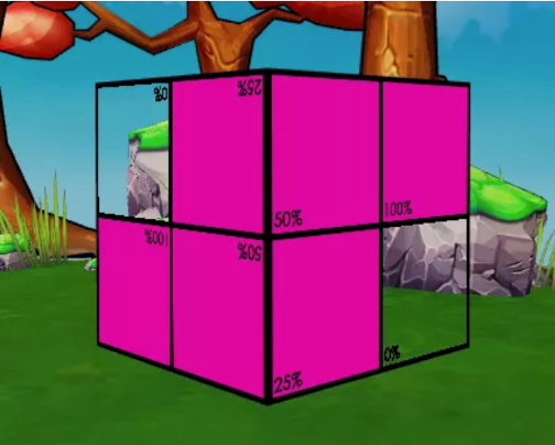
Note: the full transparency test is still used here, discarding the 0% lattice fragment.
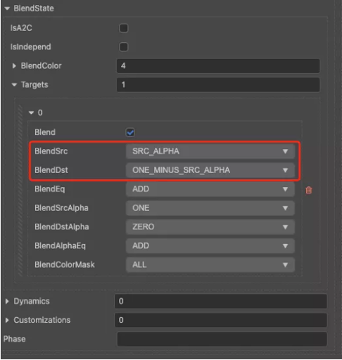
At this point, you can observe that the rest of the grid with transparency is still rendered like a grid without transparency, which is the effect of not turning on blending. Here we choose to use the transparency provided by the texture, so we choose SRC_ALPHA for the source factor blendSrc and ONE_MINUS_SRC_ALPHA for the target factor blendDST.
The equation here is expressed as follows (here the source uses a 50% transparency region (0.9, 0, 0.6, 0.5), and the color buffer is assumed to be solid green (0, 1, 0, 1))
-
color(RGB) = (0.9, 0, 0.6) * 0.5 + (0, 1, 0) * (1 - 0.5)
-
color(A) = 0.5 * 1 + 1 * 0
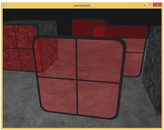
The result is a window-like effect like the following.
But here, do you find anything wrong? Why are the bottom and back of the cube missing after the blending effect? This brings us to face culling.
By default, the source and target are added in the mixed equation, but we can also modify the calculation with void gl.blendEquation(mode);. It can be summed, subtracted, vice versa, etc. Please check the related API for details as we won’t go into too much detail here.
Rendering order
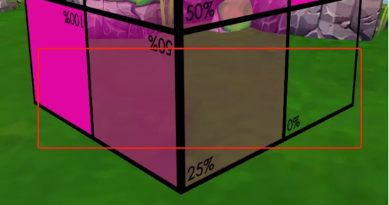
After learning about depth and blend tests, we understand that opaque objects discard fragments based on depth, while transparent objects are blended with fragments in the color buffer when the blend test is turned on. If we try to put more objects into the scene, for example, rendering a semi-transparent object first (which is closer to the camera) and then an opaque object (which is further away from the camera), it is possible that a situation will arise where this happens:
The second window on the right is invisible in the lower-left corner of the area, which seems to us to be out of place. This is the time to try to think of objects that need to be blended to turn on a depth test or perform a depth write? What should be the rendering order of non-transparent objects and transparent objects?
The general principle of the correct approach is as follows.
-
Draw all opaque objects first.
-
Order all transparent objects using the viewer’s perspective, i.e., distance from the camera, and in “most” cases, without turning on the depth test.
-
Draws transparent objects in order from far to near.
Cocos Creator 3.x version also follows this principle. But for the second point, I’ve highlighted “most” because there are special cases. For example, suppose you have two translucent objects with an interpolation effect. In that case, the top half of object A is closer to the camera, and the bottom half of object B is closer to the camera. They are in an X shape, so the bottom half of object A is obscured by the bottom half of object B, and the top half of object B is the same, but the camera recognizes the depth of the object, so you end up with an object that behaves abnormally. This situation cannot be avoided, and the ideal would undoubtedly be for the engine to be able to do mesh separation. Then at this point, the translucent object does depth detection to separate the data but can be written without depth so that the fragment is not discarded. But even if we are so ideal, there will still be some conditions that cannot meet the demand, so we can only try to avoid such a situation in the production, and the project depends on the situation.
Face Rejection
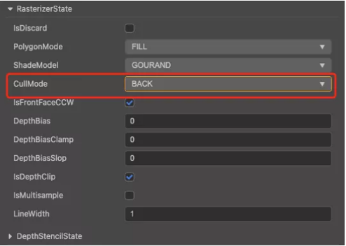
Since an object is transparent, it means that both the scene behind it and the structure inside it can be seen through it, but that doesn’t seem to be the case in reality. This is because the engine renders the back side by default, so we can see the front side of the object but not the back side no matter how we rotate it, so we need to turn on both front and back rendering. Here we can set this with a cullMode, which is under the rasterizerState state setting.
-
BACK: Cancel the back side
-
FRONT: Cancel the front side
-
NONE: Do not reject
Here, we choose NONE mode not to reject any face, and then we see the back side of the object.
Of course, the way the face rejection is set up is simple, but surely some developers would like to ask, what is the principle of this? Simply put, its core principle is the wrapping order.
Wrapping order
When defining a triangle vertex, do you remember that we defined a set of vertex index data before? The setting of this vertex index data is, in fact, deliberate. The default base layer defines the counterclockwise direction as the positive direction, so the provided vertex index order is just provided in a counterclockwise way. If clockwise is provided, it will be eliminated from view as it is here.
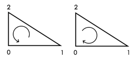
Note: The determination of counterclockwise or clockwise here is based on the rendering data provided rather than the observer view.
References
Series Summary
We have completed our text version of improving your understanding of shaders in Cocos Creator 3.x. The main purpose of this series is to take you through some shader basics and how to apply and modify them in Cocos Creator to meet some specific effects. You may not be able to “build your own car,” but you can still do the basic repair work.
Developers who are interested in shaders can also go to the official OpenGL website to see more about rendering. Of course, the basis of rendering is also inseparable from transformations (vectors and matrices), so you can take a look at 3D Math Fundamentals: Graphics and Game Development for this part.
A video series is also available from our YouTube channel. Please watch if you still need additional help. Thanks to Jone and her work building this tutorial for our Cocos Creator developers and the evangelist team for their help in the editing and research for this tutorial.