
Cocos Shader Series - Add Some Texture
Series Chapters
- Basic Introduction
- Build A Triangle
- Draw More Things
- Add Some Texture
- Draw Shaders With Cocos Creator
- Change a shader with a texture map
- Use a Noise Map to Make a Disolve Texture
- Building With WebGL
- Alpha Testing and Blending
- Blend Testing
In the first three chapters, we learned how to use WebGL to draw a triangle, combine it into a rectangle, and replace vertex data in various patterns. But all the drawn content is based on the drawing of basic primitives. If you want the drawn content to look more authentic, you need more vertices or more colors. For example, every frame needs a picture. This can be the Mona Lisa or a sunflower. At this time, we can add a texture to add more details to the object. The application of texture involves texture mapping. Texture mapping is used to map a picture to the surface of a geometric figure. For example, texture mapping to a rectangular object. This rectangle looks like a picture. This picture can also be called a texture image or texture.
Texture mapping
The function of texture mapping is to paint an appropriate color for each rasterized fragment according to the texture image. The pixels that make up the texture image are also called texels. The color of each texel can be RGB or RGBA format encoding.
Texture coordinates
In order to map a texture to an object, we need to specify which part of the texture corresponds to each vertex of the object. These textures are more often used as 2D textures, where the texture coordinates are on the x and y axes, ranging from 0 to 1. 2D texture coordinates are often called uv coordinates, where u corresponds to the horizontal or x-axis, and v corresponds to the vertical, or y-axis. In the case of 3D textures, the third one is w, which corresponds to the z-axis. The texture coordinates start at the point (0, 0), which is the lower left corner of the texture, and end at (1, 1), which is the upper right corner of the texture. The use of texture coordinates to obtain the texture color is called sampling. Each vertex is associated with a texture coordinate that indicates which part of the texture to sample from.
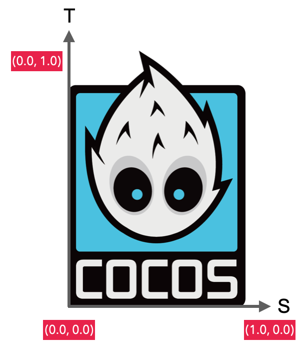
The texture coordinates look like this:
const uvs = [
    0, 0, // bottom left corner
    0, 1, // upper left corner
    1, 0, // bottom right corner
    1, 1 // upper right corner
];
The mapping principle is mainly to map the vertices of the texture image to the four vertices of the WebGL coordinate system.

Texture wrapping
The range of texture coordinates is usually from (0, 0) to (1, 1). What should I do if it exceeds this range? The default behavior of OpenGL is to repeat this texture image, but it also provides some other options:
| Surround method | Description |
|---|---|
| REPEAT | The default behavior for textures. Repeat the texture image. |
| MIRRORED_REPEAT | Same as REPEAT, but each repeated picture is placed in a mirror image. |
| CLAMP_TO_EDGE | The texture coordinates will be constrained to be between 0 and 1, and the excess part will repeat the edges of the texture coordinates, resulting in a stretched edge effect. |
// You can use gl.texParameter[fi] to set the coordinates in different axes (2D texture st corresponds to uv, 3D texture str corresponds to uvw)
// void gl.texParameterf(target, pname, param);
// For parameters, please refer to: https://developer.mozilla.org/en-US/docs/Web/API/WebGLRenderingContext/texParameter
// Since there are many application conditions, you can directly follow the link to learn them, and then you can understand the parts involved in the tutorial accordingly

gl.texParameteri(gl.TEXTURE_2D, gl.TEXTURE_WRAP_S, gl.CLAMP_TO_EDGE);
gl.texParameteri(gl.TEXTURE_2D, gl.TEXTURE_WRAP_T, gl.CLAMP_TO_EDGE);
When the texture coordinates exceed the default range, each option has a different visual effect output.
PHOTO
Note: The REPEAT mode in WebGL1 has requirements on the size of the texture image. The width and height need to be an integer power of 2, for example, 32x32, 512x512. Otherwise, a warning that it is not a power of 2 will appear during operation. WebGL2 has no such limitation.
Texture filtering
Texture coordinates do not depend on the resolution and can be any floating-point value, so OpenGL knows how to map texels to texture coordinates. However, if a small texture needs to be mapped to a large object at this time, multiple pixels may be mapped to the same texel. On the contrary, a single pixel may be mapped to multiple texels. Texture filtering is to solves the problem of texture sampling calculation when inconsistent. Among them, the most important are the following two:
-
NEAREST proximity filtering. Selecting the pixel whose center point is closest to the texture coordinates is also the simplest way of texture filtering and has the highest efficiency, as shown on the left in the figure below.
-
LINEAR filtering. The 4 nearest texels around the center point are selected to be weighted and calculated. The closer the center of a texel is to the texture coordinates, the more significant the color of this texel to the final sample color, as shown on the right in the figure below.
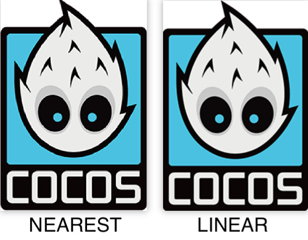
It can be seen from the figure that the image with the adjacent filter has a more apparent jagged look (such as in the eye sockets), while the image on the right is smoother. The picture I chose here is large, and with smaller sizes, it will be more obvious. Linear filtering can produce more realistic output, but you can use the proximity filtering option if you want to develop pixel-style games.
When zooming in and out of the image, we can choose different filtering options. For example: when zooming out, use proximity filtering to get the highest efficiency; when zooming in, use linear filtering to get better performance. The use of texture filtering is similar to that of texture wrapping:
// when zooming out
gl.texParameteri(gl.TEXTURE_2D, gl.TEXTURE_MIN_FILTER, gl.NEAREST);

// when zooming in
gl.texParameteri(gl.TEXTURE_2D, gl.TEXTURE_MAG_FILTER, gl.LINEAR);
Apply texture to the rectangle
Next, try to associate the texture coordinates with the rectangle in the previous chapter. First, restore all the vertex colors to white. All the codes is listed below:
function createShader(gl, type, source) {
    // ...
}

function createProgram(gl, vertexShader, fragmentShader) {
    // ...
}

function main() {
  const image = new Image();
  // If you use the built-in operating environment on the WebGL document to edit the content, you can directly use the built-in texture image of the website. https://webglfundamentals.org/webgl/resources/leaves.jpg.
  // Since I customized the local file here, I created a local server to load the image. The way to use local files is at the end of the article.

  image.src = "http://192.168.55.63:8080/logo.png";
  image.onload = function() {
    render(image);
  };
}

function render() {
    const canvas = document.createElement('canvas');
    document.getElementsByTagName('body')[0].appendChild(canvas);
    canvas.width = 400;
    canvas.height = 300;
    const gl = canvas.getContext("webgl");
    if (!gl) {
        return;
    }

    const vertexShaderSource = `
    attribute vec2 a_position;

    // Texture map uv coordinates
    attribute vec2 a_uv;
    attribute vec4 a_color;
    varying vec4 v_color;
    varying vec2 v_uv;

    // Shader entry function

    void main() {
        v_color = a_color;
        v_uv = a_uv;
        gl_Position = vec4(a_position, 0.0, 1.0);
    }`;

    const vertexShader = createShader(gl, gl.VERTEX_SHADER, vertexShaderSource);

    // Make the ratio of the vertices consistent with the ratio of the image
    const ratio = (image.width / image.height) / (canvas.width / canvas.height);
    const positions = [
        -ratio, -1,
        -ratio, 1,
        ratio, -1,
        ratio, 1
    ];

    const uvs = [
        0, 0, // bottom left corner
        0, 1, // upper left corner
        1, 0, // bottom right corner
        1, 1 // upper right corner
    ];

    // Temporarily shield the effect of color at the fragment shader text, but here we upload the color value to the vertex shader
    const colors = [
        255, 0, 0, 255,
        0, 255, 0, 255,
       0, 0, 255, 255,
        255, 127, 0, 255
    ];

    const indices = [
        0, 1, 2,
        2, 1, 3
    ];

    const vertexBuffer = gl.createBuffer();
    gl.bindBuffer(gl.ARRAY_BUFFER, vertexBuffer);
    const attribOffset = (positions.length + uvs.length) * Float32Array.BYTES_PER_ELEMENT + colors.length;
    const arrayBuffer = new ArrayBuffer(attribOffset);
    const float32Buffer = new Float32Array(arrayBuffer);
    const colorBuffer = new Uint8Array(arrayBuffer);

    // The current vertex attribute structure is pos + uv + color
    // According to float 32 distribution pos(2) + uv(2) + color(1)
    // Distribute by subsection pos(2x4) + uv(2x4) + color(4)

    let offset = 0;
    let i = 0;
    for (i = 0; i <positions.length; i += 2) {
        float32Buffer[offset] = positions[i];
        float32Buffer[offset + 1] = positions[i + 1];
        offset += 5;
    }

    offset = 2;

    for (i = 0; i <uvs.length; i += 2) {
        float32Buffer[offset] = uvs[i];
        float32Buffer[offset + 1] = uvs[i + 1];
        offset += 5;
    }

    offset = 16;

    for (let j = 0; j <colors.length; j += 4) {
        // 2 position floats, plus 4 unit8, 2x4 + 4 = 12
        // stride + offset

        colorBuffer[offset] = colors[j];
        colorBuffer[offset + 1] = colors [j + 1];
        colorBuffer[offset + 2] = colors[j + 2];
        colorBuffer[offset + 3] = colors[j + 3];
        offset += 20;
    }

    gl.bufferData(gl.ARRAY_BUFFER, arrayBuffer, gl.STATIC_DRAW);
    const indexBuffer = gl.createBuffer();
    gl.bindBuffer(gl.ELEMENT_ARRAY_BUFFER, indexBuffer);
    gl.bufferData(gl.ELEMENT_ARRAY_BUFFER, new Uint16Array(indices), gl.STATIC_DRAW);
    const fragmentShaderSource = `
    precision mediump float;
    varying vec2 v_uv;
    varying vec4 v_color;

    // GLSL has a built-in data type for texture objects, called Sampler, which uses the texture type as a suffix
    // For example, if 2D texture is used here, the type is defined as sampler2D

    uniform sampler2D u_image;

    // Shader entry function
    void main() {

        // Use the GLSL built-in function texture2D to sample the texture, its first parameter is the texture sampler, and the second parameter is the corresponding texture coordinates
        // The function will use the previously set texture parameters to sample the corresponding color values. The output of this fragment shader is the (filtered) color on the (interpolated) texture coordinates of the texture.

        gl_FragColor = texture2D(u_image, v_uv);
    }`;

    const fragmentShader = createShader(gl, gl.FRAGMENT_SHADER, fragmentShaderSource);
    const program = createProgram(gl, vertexShader, fragmentShader);
    gl.viewport(0, 0, gl.canvas.width, gl.canvas.height);
    gl.clearColor(0, 0, 0, 255);
    gl.clear(gl.COLOR_BUFFER_BIT);
    gl.useProgram(program);

    const positionAttributeLocation = gl.getAttribLocation(program, "a_position");
    gl.enableVertexAttribArray(positionAttributeLocation);

    const uvAttributeLocation = gl.getAttribLocation(program, "a_uv");
    gl.enableVertexAttribArray(uvAttributeLocation);

    const colorAttributeLocation = gl.getAttribLocation(program, "a_color");
    gl.enableVertexAttribArray(colorAttributeLocation);
    gl.bindBuffer(gl.ARRAY_BUFFER, vertexBuffer);
    gl.vertexAttribPointer(positionAttributeLocation, 2, gl.FLOAT, false, 20, 0);

    // Added vertex attribute texture coordinates, everyone should be clear here, so I won’t say more
    gl.vertexAttribPointer(uvAttributeLocation, 2, gl.FLOAT, false, 20, 8);
    gl.vertexAttribPointer(colorAttributeLocation, 4, gl.UNSIGNED_BYTE, true, 20, 16);

    const texture = gl.createTexture();
    gl.bindTexture(gl.TEXTURE_2D, texture);

    // Set the wrapping method of the texture
    gl.texParameteri(gl.TEXTURE_2D, gl.TEXTURE_WRAP_S, gl.CLAMP_TO_EDGE);
    gl.texParameteri(gl.TEXTURE_2D, gl.TEXTURE_WRAP_T, gl.CLAMP_TO_EDGE);

    // Set the filter method of the texture
    gl.texParameteri(gl.TEXTURE_2D, gl.TEXTURE_MIN_FILTER, gl.NEAREST);
    gl.texParameteri(gl.TEXTURE_2D, gl.TEXTURE_MAG_FILTER, gl.LINEAR);

    // gl.texImage2D(target, level, internalformat, format, type, HTMLImageElement? pixels);

    // This interface is mainly used to specify two-dimensional texture images. There are many sources of images, and HTMLCanvasElement, HTMLImageElement or base64 can be used directly. Here choose the most basic HTMLImageElement to explain
    // For details on the parameters, please refer to: https://developer.mozilla.org/en-US/docs/Web/API/WebGLRenderingContext/texImage2D

    gl.texImage2D(gl.TEXTURE_2D, 0, gl.RGBA, gl.RGBA, gl.UNSIGNED_BYTE, image);
    gl.bindBuffer(gl.ELEMENT_ARRAY_BUFFER, indexBuffer);
    gl.drawElements(gl.TRIANGLES, indices.length, gl.UNSIGNED_SHORT, 0);
}
Eventually, we will see such an image on the screen.

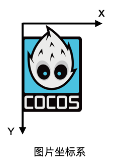
The picture is upside down because the picture itself also has a coordinate system in addition to the texture coordinates. The origin of the picture’s coordinates starts at the upper left corner and ends at the lower right corner. The value range is also 0-1. Load a picture into the texture, and the picture data will go from the picture coordinate system to the texture coordinate system. The picture has appeared upside down at this time, so we need a flipY operation, which will be upside down again when rendering.
// Flip the picture
gl.pixelStorei(gl.UNPACK_FLIP_Y_WEBGL, true);
Some students may ask why sampler2D is a uniform, but it does not need to be assigned by gl.uniform. Because in OpenGL, a default texture location is assigned to the texture, which is called a texture unit. The texture unit activated by default is 0, so I did not perform any position value assignment before, and the texture map will automatically be bound to the default texture unit. Of course, we can also use gl.uniform to set multiple textures to the fragment shader and only need to activate the corresponding texture unit. General equipment supports 8 texture units, and modern mid-to-high-end equipment supports more. This can only be analyzed for specific models. Generally, it is limited to 8 texture units. Their numbers are gl.TEXTURE0-8. This numbering method will be very convenient for us to loop the texture unit, but this is a later story.
Next, we try to add one more texture. Make the following transformations on the original code:
function main() {
    // Add a new texture map
    const images = ["http://192.168.55.63:8080/logo.png", "http://192.168.55.63:8080/close-icon.png"];
    const dataList = [];
    let index = 0;
    for (let i = 0; i <2; i++) {
        const image = new Image();
        image.src = images[i];
        dataList.push(image);
        image.onload = function () {
            index++;
            if (index >= images.length) {
                render(dataList);
            }
        };
    }
}

function render(dataList) {
    // ...
    // Redefine the vertex position
    const ratio = 0.5;
    const positions = [
        -ratio, -1,
        -ratio, 1,
        ratio, -1,
        ratio, 1
    ];

    // ...

    // Modify the fragment shader text
    const fragmentShaderSource = `
    precision mediump float;
    varying vec2 v_uv;
    varying vec4 v_color;

    // add a texture
    uniform sampler2D u_image0;
    uniform sampler2D u_image1;

    // Shader entry function
    void main() {
        vec4 tex1 = texture2D(u_image0, v_uv);
        vec4 tex2 = texture2D(u_image1, v_uv);

        // Multiply the texture color values
        // Multiplying rgb and black is black (each component of black rgb is 0), and multiplying white, it is primary color (each component of white rbg is 1)

        gl_FragColor = tex1 * tex2;
    }`;

    // ...

    // Set the flip when it is judged that there is a texture
    if(dataList.length> 0){
        gl.pixelStorei(gl.UNPACK_FLIP_Y_WEBGL, true);
    }

    for (let j = 0; j <dataList.length; j++) {
        const data = dataList[j];
        const samplerName = `u_image${j}`;
        const u_image = gl.getUniformLocation(program, samplerName);

        // Set the position value of each texture

        gl.uniform1i(u_image, j);
        const texture = gl.createTexture();
        gl.activeTexture(gl.TEXTURE0 + j);
        gl.bindTexture(gl.TEXTURE_2D, texture);
        gl.texParameteri(gl.TEXTURE_2D, gl.TEXTURE_WRAP_S, gl.CLAMP_TO_EDGE);
        gl.texParameteri(gl.TEXTURE_2D, gl.TEXTURE_WRAP_T, gl.CLAMP_TO_EDGE);
        gl.texParameteri(gl.TEXTURE_2D, gl.TEXTURE_MIN_FILTER, gl.NEAREST);
        gl.texParameteri(gl.TEXTURE_2D, gl.TEXTURE_MAG_FILTER, gl.LINEAR);
        gl.texImage2D(gl.TEXTURE_2D, 0, gl.RGBA, gl.RGBA, gl.UNSIGNED_BYTE, data);
    }
}
Comparison of the original image and the rendered image

So far, I believe you should understand how texture mapping works. Next, let’s look at a few more use cases.
More cases
The several cases shown here are still presented according to one texture.
Different vertex colors are applied to the texture
Believe that if you follow to learn this, you can easily achieve it, right?
// Part of the application code is shown here
const colors = [
    255, 0, 0, 255,
    0, 255, 0, 255,
   0, 0, 255, 255,
    255, 127, 0, 255
];

const fragmentShaderSource = `
precision mediump float;
varying vec2 v_uv;
varying vec4 v_color;
uniform sampler2D u_image;

void main() {
    vec4 tex1 = texture2D(u_image, v_uv);
    gl_FragColor = tex1 * v_color;
}`;

Add a little more detail, and it feels like a laser card.
Change the RGB order of the final output
const fragmentShaderSource = `
precision mediump float;
varying vec2 v_uv;
varying vec4 v_color;
uniform sampler2D u_image;

void main() {
    vec4 tex1 = texture2D(u_image, v_uv).bgra;
    gl_FragColor = tex1;
}`;

This example replaces the color of the original channel with another color.
There are many examples of texture applications on the Internet, and everyone can try to remodel them.
Why are variables prefixed with a_, u_, or v_ in GLSL?
This is a naming convention, not mandatory. But this is used to more clearly share where the value should come from. For example, a_ refers to the vertex input attribute, which means the data comes from the vertex buffer. u_ is the global variable uniform, which can be directly matched to the shader settings. v_ represents the variable, which is interpolated from the vertices of the vertex shader.
Local server setup
Because I’ll be creating WebGL test content for this tutorial, I put it all in a custom folder. Therefore, a server is needed to run HTML files. The contents of the folder are as follows:

Next, install the npm library http-server under the folder:
npm install http-server -g

// Execute after installation
http-server

// At this time, the console will appear and will show something similar to the following:
Available on:
  http://127.0.0.1:8080
  http://192.168.55.63:8080
Just choose one of the addresses to use, but you can’t mix them, or cross-domain problems may occur. For example, I use “http://192.168.55.45:8080” to open the project, and then this address is also used for image loading.
Finally, enter the address on the browser:
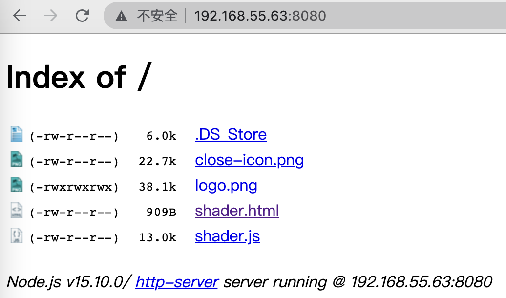
Click the html file to test.
Note: If you are prompted that there is no npm name, it may be because you have not installed any version of Node.js. Please install Node.js. If the network is switched and the IP address has changed, remember to re-execute the http-server to regenerate the local server.