
Cocos Shader Series - Build A Triangle
Series Chapters
- Basic Introduction
- Build A Triangle
- Draw More Things
- Add Some Texture
- Draw Shaders With Cocos Creator
- Change a shader with a texture map
- Use a Noise Map to Make a Disolve Texture
- Building With WebGL
- Alpha Testing and Blending
- Blend Testing
…
In the previous chapter, some basic concepts of WebGL were introduced. To sum up, in two sentences, WebGL’s work on the GPU is divided into two parts. The first part is to convert vertices (or data streams) to clipping space coordinates, and the second part is to draw pixels based on the results of the first part. This chapter focuses on understanding the role of vertex shaders and fragment shaders in the rendering pipeline.
This chapter will focus on rendering a triangle and learn about the rendering knowledge involved.
Render a triangle
Vertex input and standardized device coordinates
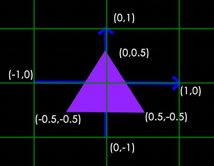
Before we start drawing graphics, we must first enter some vertex data into WebGL. If we want to render a plane triangle, we need to specify three vertices, and each vertex has a two-dimensional position, which is stored in the form of an array.
var positions = [
    0, 0,
    0, 0.5,
    0.7, 0,
];

// Because it is a flat triangle, there is no depth (z)
Here, there is something to be said about why such values are used. One of the things you need to know here is the normalized device coordinates. The standardized device coordinates are the coordinates that are processed by the vertex shader, and each component of the coordinates must be between -1 and 1. Therefore, all the coordinates we set ourselves must be transformed into normalized device coordinates, which are passed to the rasterizer to transform into two-dimensional coordinates or pixels on the screen, which eventually evolve into the picture we see. The cropped coordinates in our coordinate conversion stage are the basis for cropping the values beyond the normalized device coordinates to form the actual vertex values used. Since this chapter focuses on the rendering process, instead of using the local coordinates commonly used in games, we will use the crop coordinates directly.
Write rendering code
With such a set of vertex data, it can be sent as input to the first stage of the graphics rendering pipeline: the vertex shader. WebGL will create memory on the GPU to store vertex data, and then analyze this memory in combination with vertex combinations. WebGL manages this memory through a vertex buffer object (VBO), which stores a large number of vertices in the GPU memory (video memory) for use by the vertex shader. Next, we try to submit the vertex data to the GPU.
<body>
// If you are using a browser such as chrome to test an independent html file, you need to run the script, otherwise you don’t need to add the following sentence
<script src="./shader.js"></script>
</body>

"use strict";

// Start from the main function
// Create a shader shader.gl: WebGL context; type: shader type; source: shader text
function createShader(gl, type, source) {

// Create shader based on type
var shader = gl.createShader(type);

// Binding content text source
gl.shaderSource(shader, source);

// compile shader (convert text content into shader)
gl.compileShader(shader);

// Get the compiled state
var success = gl.getShaderParameter(shader, gl.COMPILE_STATUS);

if (success) {
        return shader;
    }

    // Get information about the current shader
    console.log(gl.getShaderInfoLog(shader));

    // Delete the shader that failed
    gl.deleteShader(shader);
}

// Create a coloring program program. gl: WebGL context; vertexShader: vertex shader object;
fragmentShader: fragment shader object
function createProgram(gl, vertexShader, fragmentShader) {

// Create a coloring program
var program = gl.createProgram();

// Let the shader get the vertex shader
gl.attachShader(program, vertexShader);

// Let the shader program get the fragment shader
gl.attachShader(program, fragmentShader);

// Bind the two shaders to the shader program
gl.linkProgram(program);
var success = gl.getProgramParameter(program, gl.LINK_STATUS);

if (success) {
      return program;
}

    console.log(gl.getProgramInfoLog(program));

    // If the binding fails, delete the shader
    gl.deleteProgram(program);
}

function main() {

    // Step 1: Get gl

    // Create canvas
    const canvas = document.createElement('canvas');
    document.getElementsByTagName('body')[0].appendChild(canvas);
    canvas.width = 400;
    canvas.height = 300;

    // Get the WebGL context (Context), which will be collectively referred to as gl in the following.
    const gl = canvas.getContext("webgl");
    if (!gl) {
        return;
    }

    // Step 2: Vertex Shader

    // Define vertex shader text
    const vertexShaderSource = `

    // Receive vertex position data
    attribute vec2 a_position;

    // Shader entry function
    void main() {
        // gl_Position receives a vec4, so it needs to be converted
        gl_Position = vec4(a_position, 0.0, 1.0);
    };

      // Create a shader object that can be used on WebGL according to the content of the shader text
    const vertexShader = createShader(gl, gl.VERTEX_SHADER, vertexShaderSource);

    // Customize the cropping coordinates. Still take the drawing of triangles as an example to provide vertex data. Because it is a plane triangle, only one vec2 is provided for each vertex.
    const positions = [
        0, 0,
        0, 0.5,
        0.7, 0,
    ];

    // Create a vertex buffer object
    const vertexBuffer = gl.createBuffer();

    // Bind the vertex buffer object to the ARRAY_BUFFER field of gl.
    gl.bindBuffer(gl.ARRAY_BUFFER, vertexBuffer);

    // Store the current vertex data into the buffer (vertexBuffer) through bufferData
    // As mentioned before, there are many default states in gl, so the vertex buffer that needs to be clearly stored at this time is my custom buffer. Data storage in the GPU needs to be very careful, otherwise, it may cause a waste of memory.

    // Next, you need to clarify the data size, where each component of the vertex coordinates is stored in 32-bit floating-point data. We need to allocate memory for each type of data reasonably.

    // The last parameter gl.STATIC_DRAW is to prompt WebGL on how we will use these data. Because we have written the vertex data to death, we use gl.STATIC_DRAW.
    // gl.STATIC_DRAW: The data will not or hardly change.
    // gl.DYNAMIC_DRAW: The data will be changed a lot.
    // gl.STREAM_DRAW: The data will change every time it is drawn

    gl.bufferData(gl.ARRAY_BUFFER, new Float32Array(positions), gl.STATIC_DRAW);

    // Step 3: Fragment shader

    // Similar to vertex shader operation
    // Get the fragment shader text

    const fragmentShaderSource = `
    precision mediump float;

    // Shader entry function

    void main() {
        // Fix the final color of the triangle output to rose red
        // The four components here represent red (r), green (g), blue (b) and transparency (alpha)
        // The color value is the normalized value. The final drawing is actually [255, 0, 127. 255]

        gl_FragColor = vec4(1, 0, 0.5, 1);

    }`;

    const fragmentShader = createShader(gl, gl.FRAGMENT_SHADER, fragmentShaderSource);

    // Step 4: Coloring procedure

    // Bind the vertex shader and fragment shader to the shader program.
    // As mentioned in the previous chapter, shading programs need to be provided in pairs, one of which is a vertex shader and the other is a fragment shader

    const program = createProgram(gl, vertexShader, fragmentShader);

}
Note: please review a tutorial on WebGL online site for practice if needed.
So far, the input vertex data has been sent to the GPU and instructed the GPU how to process it in the vertex shader. We’re almost done, but it’s not over yet. WebGL doesn’t know how it interprets the vertex data in memory or how it links the vertex data to the attributes of the vertex shader. We need to tell WebGL what to do.
Note: The advantage of using the vertexBuffer buffer object is that a large amount of data can be sent to the graphics card at one time, rather than once per vertex. Sending data from the CPU to the graphics card is relatively slow, so try to send as much data as possible at once whenever possible. When the data is sent to the graphics card’s memory, the vertex shader can access the vertices almost immediately, which is a very fast process.
Vertex data analysis
The vertex shader allows specifying any input in the form of vertex attributes. That is to say, a vertex can contain multiple attributes. This form of input provides us with great flexibility in data organization. A float 32-bit vertex buffer data will be parsed as follows:
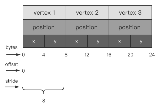
This is the most basic structure of vertex buffer data, filled only by position data. This is where:
-
Each vertex position contains 2 position components. Since the buffer is a float 32-bit floating-point array, one byte is 8 bits, so the difference between each vertex component by byte is 4 bytes.
-
The offset represents the offset of the current input data in a vertex data. If there are vertex colors, texture coordinates, etc., then the offset should be selected according to the data structure, and the offset is provided in the form of “data offset length x number of bytes”.
-
The stride represents the total byte length of vertex data and is calculated as vertex data length * sizeof(float). For example, if a position has 2 components and uses float 32-bit floating-point data, the number of bytes it takes up is 2x4 = 8.
After understanding this, then, Continue to color content:
function main() {
    ...
    const program = createProgram(gl, vertexShader, fragmentShader);

    // Step Five: Processing the pre-work of drawing

    // Set the viewport size, synchronize the viewport and canvas size
    gl.viewport(0, 0, gl.canvas.width, gl.canvas.height);

    // Clear the canvas color and directly set it to a transparent color. Here is to facilitate the observation, set it to black.
    // Note that the rendering pipeline draws content every frame, just like drawing on the artboard every frame. If you don't clear it, there may be a phenomenon of blurring.

    gl.clearColor(0, 0, 0, 255);
    gl.clear(gl.COLOR_BUFFER_BIT);

    // Step 6: Start the program, enable vertex attributes

    // enable the shading program we currently need
    gl.useProgram(program);

    // Query where the vertices are going, and enable attributes
    const positionAttributeLocation = gl.getAttribLocation(program, "a_position");
    gl.enableVertexAttribArray(positionAttributeLocation);

    // Bind the vertex buffer to the current data buffer interface, so that the buffers for subsequent operations are the buffers currently bound. Bind it every time you need to use data.
    gl.bindBuffer(gl.ARRAY_BUFFER, vertexBuffer);

    // Step 7: Tell the attribute how to get the data

    // gl.vertexAttribPointer(positionAttributeLocation, size, type, normalize, stride, offset);
    // positionAttributeLocation: Get the position of the "a_position" attribute on the vertex shader
    // size: The length of the data to be taken in the current vertex data. Because the plane triangle is drawn, the position only needs to provide x, y, so the number is 2
    // type: data buffer type, here the vertex is float 32, so use gl.FLOAT
    // normalize: whether the data is normalized data, usually not
    // stride: Mainly express the way of data storage. The unit is a byte. 0 means that the attribute data is stored continuously, which is usually used in data with only one attribute
    // Non-zero means the interval size of the same attribute in the data, which can be understood as the step size. This will be reflected in the following description
    // offset: the offset value of each interval of the attribute in the buffer, the unit is byte

    gl.vertexAttribPointer(positionAttributeLocation, 2, gl.FLOAT, false, 0, 0);

    // Step eight: draw

    // gl.drawArrays(primitiveType, offset, count);
    // primitiveType: Specifies the drawing form of primitives. The common ones are drawing points (gl.POINTS), lines (gl.LINE_STRIP), and triangles (gl.TRIANGLES). Draw a triangle here.
    // offset: From which point to start drawing
    // count: how many points will be used in this drawing. It also means that the vertex shader needs to be run several times. The vertex shader only processes one vertex at a time.

    gl.drawArrays(gl.TRIANGLES, 0, 3);

    // So far, the drawing process has officially started, and the subsequent processing is handed over to the vertex shader and fragment shader

}

// execute code

main();
After writing the above content, you can run it to see the final result. If you don’t know how to build a Web runtime environment, you can find the code editing window on the WebGL official website below the link and edit it.
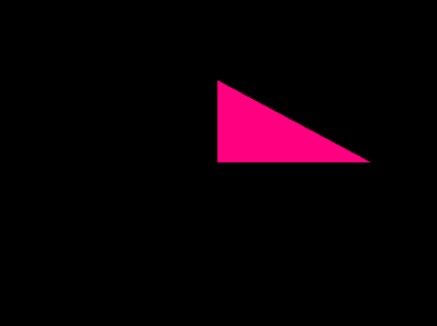
Note: for the convenience of observation, the color of clearColor is cleared to black, so the background is black.
We can see that we have successfully drawn a triangle. So far, we have completed the first step of rendering and officially entered this threshold. In the next chapter, I will continue to make some supplements to the content of this chapter to deepen the consolidation of the content of this chapter