
Cocos Shader Series - Building With WebGL
Series Chapters
- Basic Introduction
- Build A Triangle
- Draw More Things
- Add Some Texture
- Draw Shaders With Cocos Creator
- Change a shader with a texture map
- Use a Noise Map to Make a Disolve Texture
- Building With WebGL
- Alpha Testing and Blending
- Blend Testing
From the last chapter, we have already talked about the essential content of the shader. The most important part is how to compare the application of WebGL to Cocos Creator. Because the underlying rendering of all game development tools encapsulates the graphics rendering API, as long as you know the principle, you can easily use different game development tools to create the desired effect. This chapter will make some additions and extensions to the previous content.
Runtime material modification
In Chapter 6, we talked about the configurable parameters included in the material:
- effectAsset or effectName: The effect resource reference, which specifies which EffectAsset describes for rendering. (Required)
- technique: Specify which technique in EffectAsset to use, and the default is the 0th technique.
- defines: A list of macro definitions, which specify which macro definitions are turned on, and all are turned off by default.
- states: The pipeline state overload list specifies the overloads of the rendering pipeline state (deep template transparent blending, etc.). The default is consistent with the effect statement.
Therefore, here is an attempt to create the previously defined shader foo in code and set the previous operations on the editor in the form of code:
import { _decorator, Component, Node, Sprite, Material, SpriteFrame, gfx, Texture2D, EffectAsset } from 'cc';
const { ccclass, property } = _decorator;
const { BlendFactor, CullMode } = gfx;

@ccclass('Example')
export class Example extends Component {
    @property(EffectAsset)
    foo: EffectAsset = null!;
    @property(Texture2D)
    dissolveMap: Texture2D = null!;

    start () {
        const sprite = this.getComponent(Sprite);
        const mat = new Material();
        // effect name 适用于内置 shader,可以通过 EffectAsset.get('effect name') 方式获取,判断
        mat.initialize({
            effectAsset: this.foo,
            defines: {
                USE_TEXTURE: true,
            },
            states: {
                blendState:{
                    targets: [
                        {
                            blend: true,
                            blendSrc: BlendFactor.SRC_ALPHA,
                            blendDst: BlendFactor.ONE_MINUS_SRC_ALPHA,
                            blendDstAlpha: BlendFactor.ONE_MINUS_SRC_ALPHA
                        }
                    ]
                },
                rasterizerState: {
                    cullMode: CullMode.NONE,
                }
            }
        });

        sprite.customMaterial = mat;
        mat.setProperty('u_dissolveMap', this.dissolveMap!);
        mat.setProperty('dissolveThreshold', 0.3);
    }
}
If you need to modify it at runtime, you can dynamically modify it in the following ways:
// Materials can be obtained on all components with materials. The materials obtained through comp.material are usually  MaterialInstance material instances.
// The difference between Material and MaterialInstance is that MaterialInstance has always belonged to the only component from the moment it is mounted, and only takes effect on the component model, while Material has no such restriction and can belong to multiple components of the same type or different Type component
// Only MaterialInstance can dynamically modify defines and states at runtime

const sprite = this.getComponent(Sprite);
const mat = new Material();
 mat.initialize({
    effectAsset: this.foo,
});
const matInst = sprite.material;

matInst.recompileShaders({ USE_TEXTURE: true });
matInst.overridePipelineStates({
    blendState:{
        targets: [
            {
                blend: true,
                blendSrc: BlendFactor.SRC_ALPHA,
                blendDst: BlendFactor.ONE_MINUS_SRC_ALPHA,
                blendDstAlpha: BlendFactor.ONE_MINUS_SRC_ALPHA
            }
        ]
    },
    rasterizerState: {
        cullMode: CullMode.NONE,
    }
});
matInst.setProperty('u_dissolveMap', this.dissolveMap!);
matInst.setProperty('dissolveThreshold', 0.3);
UBO memory layout
UBO (Uniform Buffer Object) is a uniform buffer object. It has the same function as a normal uniform, except that it can manage one or more uniform data at a time. It replaces the way of gl.uniform to transfer data. It will no longer occupy the uniform storage space of the shaderProgram itself and store more uniform variables.
When it comes to UBO, it is necessary to mention the Uniform Blocks in the shading language GLSL (the last chapter mentioned that the uniform is declared in the block), which brings together a large number of uniform type variables for unified management. For a large number of uniform types, Variable procedures can significantly improve performance. Compared with the traditional way of setting a single uniform variable, it has the following characteristics:
1.Can store more uniform type variables
2.Can simplify the process of setting a large number of uniform variables
3.You can quickly update the value of the uniform type variable in the program in a single shading language program by switching between different UBO bindings
4.All uniform variables can be updated by updating the data in UBO in different shading language programs
// General uniform declaration
uniform float dissolveThreshold;

// UBO formal statement
uniform Dissolve{
    float dissolveThreshold;
};
It is stipulated in Cocos Creator that all non-sampler uniforms of the shader should be declared in block form. Considering that UBO is the only basic unit for efficient data reused in the rendering pipeline, a discrete declaration is no longer an option. Therefore, a uniform declaration has more stringent requirements for data distribution, such as:
- There should be no vec3 members.
- For members of array type, the size of each element cannot be less than vec4
- Any member declaration order that introduces padding is not allowed
Among them, the rules of padding are:
- All vec3 members will be filled to vec4
uniform ControversialType {
  vec3 v3_1; // offset 0, length 16 [IMPLICIT PADDING!]
}; // total of 16 bytes
- Any array and structure whose length is less than vec4 will fill in the elements to vec4
uniform ProblematicArrays {
  float f4_1[4]; // offset 0, stride 16, length 64 [IMPLICIT PADDING!]
}; // total of 64 bytes
- The actual offset of all members in UBO will be aligned according to the number of bytes occupied by themselves
uniform IncorrectUBOOrder {
  float f1_1;                    // offset 0, length 4 (aligned to 4 bytes)
  vec2 v2;                       // offset 8, length 8 (aligned to 8 bytes) [IMPLICIT PADDING!]
  float f1_2;                    // offset 16, length 4 (aligned to 4 bytes)
};                               // total of 32 bytes

// As you can see, in the above declaration method, v2 is aligned with vec2, that is, the initial calculation is offset by two floats, which is 8 bytes. So 4 bytes between 4-7 are wasted
// Since f1_1 and v2 have already occupied a vec4 storage space, f1_2 needs to open a new vec4 memory space
//So, the correct way is as follows

uniform CorrectUBOOrder {
  float f1_1; // offset 0, length 4 (aligned to 4 bytes)
  float f1_2; // offset 4, length 4 (aligned to 4 bytes)
  vec2 v2; // offset 8, length 8 (aligned to 8 bytes)
}; // total of 16 bytes
WebGL Frame Capture Tool
Before explaining the WebGL frame grabber tool, we must first know what DrawCall is. A DrawCall means that the CPU sends a drawing instruction to the GPU once. If 80 objects need to be drawn in the scene, it may be necessary to submit about 80 DrawCalls, which means that the GPU needs to draw 80 times in a rendering frame. If the DrawCall is too high, it will directly affect the game’s overall performance, causing problems such as lag. So you need to know the DrawCall information and merge and submit as much node data as possible. Therefore, we need a tool to help us analyze what each DrawCall draws so that we can take appropriate methods to optimize the data so that the same rendering data can be merged. This tool is also called a frame grab tool.
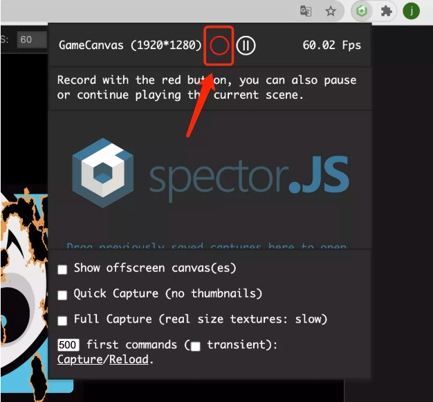
Spector.js is a good DrawCall analysis tool on the Web, which can be downloaded directly on the google store. After installing this plug-in, you can see this icon in the upper right corner of the chrome browser.

When the game is running, click this button to enable the frame grabber tool. The button will also be highlighted at this time. Click the button again, click the button in the red frame, and the current frame rendering page will pop up.
On this page, you can see what the current frame rendering has done. On the left, you can click to switch between different drawing commands and observe the changes in the interface view after each gl command is executed. The gl command is executed in the middle. On the right, you can view the detailed content of a drawing command, slide down to see similar state Data, and which vertex input attributes and uniform attributes are submitted.
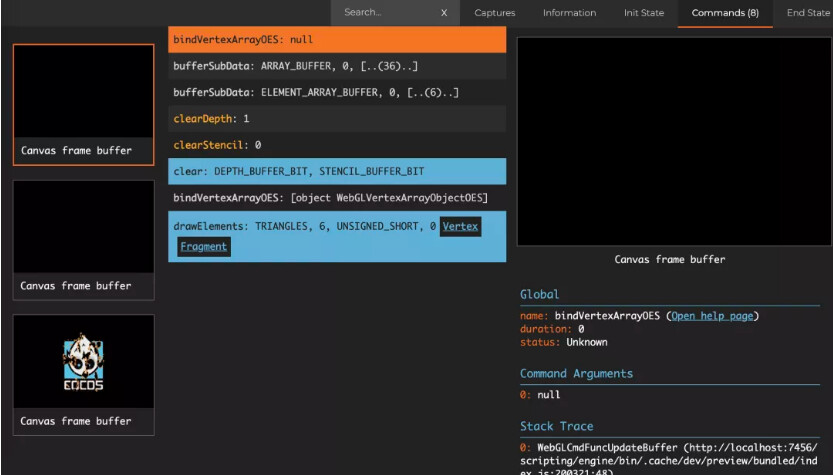
You can also see the button to jump to the vertex shader and fragment shader at the gl instruction in the middle if it is a drawing instruction. In the upper right corner, there are some status and information panel switches. You can understand by clicking on it yourself.
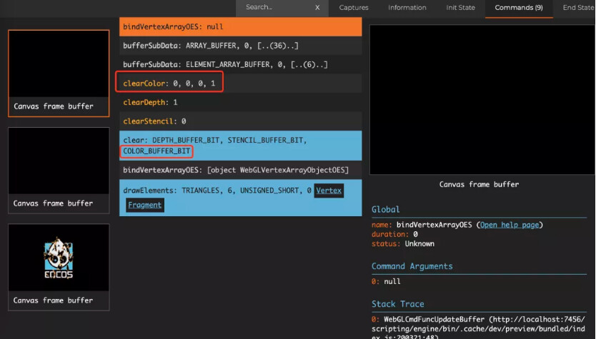
As can be seen from the figure, there are no commands such as clear or clearColor. As mentioned before, all related to clear are on the camera. There is an attribute ClearFlags on the camera that is used to handle the clear behavior. Their respective roles are:
-
DONT_CLEAR: Do not perform any draw clear -
DEPTH_ONLY: Only perform deep clearing -
SOLID_COLOR: clear the color, depth, and template buffer -
SKYBOX: enable skybox, only clear depth
There must be a camera in a scene to perform the SOLID_COLOR operation. Since Cocos Creator 3.x is a tool that emphasizes 3D development, 2D content is displayed in front of 3D content, so the 2D camera will not actively perform the SOLID_COLOR operation. However, like our case this time, there is only 2D content in the scene, so you can let the 2D camera execute SOLID_COLOR, which is the clear operation of gl. Next, change the clearFlags of the 2D camera to SOLID_COLOR, and then observe again.
I suggest everyone here, when using Spector.js, it is recommended to use the rendering backend of WebGL1. You can see a little more information. WebGL2 will omit part of the information, and the problem cannot be seen intuitively. By Project Settings → Crop function to select the rendering backend.