
Tutorial: Cocos Creator - Physics in 3D explained
The Chinese team shared a great article explaining the Cocos Creator 3.0 3D physics in detail. We felt this would help to give a quick idea on new developments with our framework and making physics development a bit easier with great performance.
Please note that the documentation is continuously updating. Always check our newest documentation and ask for support on our forums and Discord if you need help.
The following content mainly explains the functions and technical principles used in it. The space is limited and cannot cover all the details, but most of the content is introduced in the engine documentation and can be read together.
01 Select engine
For the development of 3D physics applications in Creator, the first step is to choose the physics engine. Currently, there are three options available, namely builtin, cannon.js, and bullet (ammo.js). The main difference between them is the package size, performance and functional characteristics.
| Physics engine | Features |
|---|---|
builtin |
Extremely lightweight collision detection system, only supports box, ball, capsule shape and trigger event |
cannon.js |
The physics engine developed by pure js supports most features and is easy to extend, but the performance is not good enough. The package size is about 141 KB |
ammo.js |
Compiled by bullet physics engine, it supports all features and has the best performance, but the package size is large and not easy to extend. The package size of the js version is about 1.32 MB, and the package size of the wasm version is about 690 KB. |
The main functional features are as follows:
| Features | builtin | cannon.js | ammo.js |
|---|---|---|---|
| Centroid | |||
| Box, ball | |||
| capsule | Can be pieced together with basic shapes | ||
| Convex hull | |||
| Static terrain, static plane | |||
| Static grid | Extremely limited support | ||
| Cone, cylinder |
|
||
| Simplex | Limited support | ||
| Compound shape | |||
| Radiation detection, mask filtering | |||
| Multi-step simulation, collision matrix | |||
| trigger event | |||
| Automatic sleep | |||
| Collision events, collision data | |||
| Physical material | |||
| Static and kinematics | |||
| dynamics | |||
| Point-to-point, hinge constraint (experimental) | |||
| wasm |
02 Concept explanation
The following introduces you to the more important components and functions of the physical module.
| Rigid body type | Description |
|---|---|
| Static | Static rigid body, which can be used to describe static buildings, and only generate events with Dynamic and Kinematic objects |
| Dynamic | A dynamic rigid body can be subjected to force, and the physics engine will take over the movement of the object and manipulate it through the value of the physics layer |
| Kinematic | Kinematic rigid body, usually used to express the movement of platforms such as elevators, manipulated by modifying and transformingthe transformation information |
In the figure below, white is static, blue is kinematics, and yellow is dynamics. Among them, white and blue are both manipulated transformation information, and it is obvious to see the following manifestations:and several manifestations are clearly visible.
-
There will be penetration between white and blue
-
White static objects can also move
-
The two yellow squares behave differently. The one above the white is still and the one above the blue follows the movement.
The reasons for the above phenomenon are:
- Static and kinematics are not affected by force, penetration occurs, which is normal
- Static objects can indeed move. Static means that in time and space, every moment is static, and the state at other moments will not be considered.
- Different from static objects, kinematic objects will estimate the state of motion (such as speed) based on the nearby moments, and because of friction, they drive the yellow square
RigidBody / Collider / Trigger
| Component type | Description |
|---|---|
| Rigid body component (RigidBody) | It is responsible for manipulating the motion-related properties of physical objects and configuring groupings, one node at most |
| Collider component (Collider) | It is responsible for manipulating shape-related attributes on physical objects, and a node can have multiple |
| Trigger | It is the collider component with IsTrigger checked. It penetrates other objects like a ghost, and provides events for the start, hold, and end of penetration |
Whether it is necessary to add rigid body components is the most questioned, here is a little trick:
- Add when it needs to configure grouping.
- Add when it needs to be set to kinematics or dynamics type (not adding means static type), and add a Raycast, Mask Filter, and/or Collision Matrix.
| Module | Description |
|---|---|
| Raycast | Use rays to detect collisions with other collision bodies, and record the corresponding collision data |
| Mask Filter | Use bit operation to realize whether two objects filter each other, an important collision detection optimization technology |
| Collision Matrix | It is used to initialize the grouping and mask of objects, and is the upper encapsulation of mask filtering |
There are still many areas that need to be polished in this framework. For example, some developers think that configuring grouping on static objects is not convenient enough, grouping should not be separated from the node layer, and rays should not have groups.
03 Use explanation
The following example will combine several problematic scenarios in an archery game to introduce the corresponding functional characteristics and problem-solving ideas, as well as the how to solve each point involved.
Combine crosses with basic shapes-compound shapes.
In the figure below, two box shapes are used to combine a cross, and all the collision bodies on the node are combined into a cross shape. This is the most basic way to achieve a concave shape.
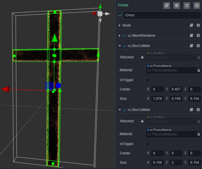
It's easy to assume that if you add collision bodies to multiple nodes to piece together the cross, that it can keep the overall structure in motion after collision. This is impossible in the current structure, and only a single node can be added.
Shooting and retrieving arrows - kinematics, dynamics, events
The first step in archery is to draw the bow. The arrow needs to completely follow the elastic string. You don’t want the arrow to be affected by the physical rules. At this time, the rigid body of the arrow should be set to the Kinematic type.
The second step is to loosen the elastic rope to launch the arrow. At this time, it is hoped that after setting the initial velocity of the arrow, it can move according to the physical rules, so set the rigid body of the arrow as the Dynamic type.
The general process of retrieving an arrow is to restore the arrow to the bow once it touches the trigger area after the arrow is shot out. This can be achieved by making a monitoring area. First, use the collider component to piece together the area, and at the same time check the collider component IsTrigger. (The blue floor in the picture below is the monitoring area).
This can be error-prone:
-
Modify the transformation information to manipulate the Dynamic type of rigid body, which should pass the value of the physical layer such as speed, force or impulse.
-
Use Static type rigid bodies to monitor events. Static rigid bodies will only generate events with rigid bodies with types of kinematics or dynamics, which can be changed to Kinematic type, or the event can be registered by the other party.
-
When listening to an event, only the OnTriggerEnter was monitored , but it was mistakenly thought to include OnTriggerStay and end OnTriggerExit
Aiming-collision matrix (filter detection), ray detection, static plane
Aiming is a step before archery. The crosshair is on the ray where the arrow points, and a static plane collider is added in front of the cross, and then the position of the crosshair can be obtained by ray detection;
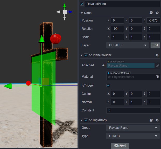
The static plane is only used for ray inspection, and a group is created for it, and it is not inspected with arrows, apples, etc., this is the most general performance optimization method.
When calling the ray detection method, set the incoming mask to only and static plane detection, that is 0b10 (binary representation).
The error-prone points are as follows:
-
Can’t distinguish the grouping on the rigid body component and the layer on the node. The concepts of the two are similar, but the uses are different. The user of the group is the physical module, and the user of the layer is the rendering module.
-
Don’t know what value to pass due to poor understanding of masks. We provide here a little skill to be able to screen out a Others mask, for example, the index value of Others is 2, which is a long binary mask from right to left of the first order 2 bit is 1, you can make Others through screening, which is ob100 (strongly recommended here to not change the index of the group)
-
Misunderstanding that the return value of the ray detection interface is the hit data. There is a special interface for obtaining the results, and the design here is to emphasize that this is a reuse object. In order to reduce garbage memory, each call to the interface will only update their data, rather than regenerate a new one (if you need a persistent record, you can clone one)
Shooting apples - static meshes, convex hulls, multi-step simulation (step size adjustment)
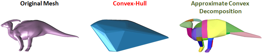
Generally, apples have concave surfaces. It is very tricky to deal with concave or continuous and smooth irregular surface models. This is because the current theories and techniques are based on the discrete and convex world (using the differential approximation to represent differentials in calculus is the most typical example).
In the real-time physics engine, such objects can only support static or kinematic rigid body levels, and there is nothing that can be done about dynamics. Unfortunately, the real Apple’s motion performance strongly relies on dynamics. In this case, you can only add a mesh collision body in the form of a convex hull to the apple (you need to convex check it) and a dynamic rigid body, using approximation object to participate in the simulation.
Kinematic performance and simulation parameters have a very strong relationship, its penetration is the most representative phenomenon, which can increase the step size and the number of steps is achieved by reducing the adjustment step is a tip: input fraction, that is 1/Frame, which Frame represents frame rate.

The error-prone points are as follows:
-
convex dynamic rigid body added to the mesh collider with the unchecked body that has penetrated with other objects, or does not react at all… This is a typical misuse. Only the checked convex one can support the dynamic rigid body.
-
Turn on a model with a very large number of vertices convex. Too many vertices will increase the number of convex hulls, which will have a great impact on performance. In fact, it is not necessary to have a convex hull with a large number of faces. It is generally recommended The number of vertices of the model should be less than 255
-
After the convex hull is turned on, the contact of the concave surface of the model is not closely correct, which is normal. The current real-time technology is to use multiple convex hulls to solve the model, as shown in the figure below:
- Only the step length is adjusted, but the number of steps is not adjusted. The two need to cooperate with each other to have an effect. The trick is that the number of steps can be set to a larger value at will, and the step length is adjusted according to the maximum speed value. The larger the value, the smaller the step length should be.
04 Motion control
The following describes how to use impact data to achieve a dynamic mechanical type of rigid body motion control.
Collision data
As shown in the figure below, the red ball indicates the location of the collision point, and the blue arrow refers to the normal of the surface where the collision point is located. The collision data needs to be obtained by the collision events (the collision data provided by the events are reused objects).
Ground judgment
Whether the character is on the ground can be known by the direction of the normal, and the corresponding condition is that normal.y > 0. Sometimes we need to know the inclination of the ground, which we can know by the size of normal.y. The closer it is to 1, then the flatter the ground is (the normal is vertically up); the closer it is to 0, then the steeper the ground is.
Jump
Once you can determine whether you are on the ground, you can add jumping behavior. The first thing to be clear is that the dynamic rigid body is used here (the reason is that I want to get more real physical feedback after taking over the rigid body through the physics engine), so we need to change the physical value to achieve the goal, such as directly linearizing the character The speed of the y component is set 5, as shown in the figure below (the collision body in the figure is a capsule body, which is related to the actual scene and can be changed by yourself).
By directly changing the y-axis speed, it can work well on a perfectly horizontal ground. But sometimes jumping needs to behave differently according to the slope of the ground. Here is an idea: provide a configuration factor, ranging from 0 to 1, and interpolate the current normal and the vertical normal according to the factor to get the target normal. And multiply by the jumping speed, then get the desired jumping speed, add it to the linear speed of the character.
Walking and standing
For standing behavior, if you want the character to not fall down, just set AngularFactor to 0. The walking behavior can be implemented according to the movement state of the character. Assuming that the character needs to be moved on the x axis, the linear velocity of the character axis is modified wherever it is x. Therefore, to control walking, only two quantities are needed, one is the movement direction and the other is the movement speed.
The only trick to make good motion control is to control the speed, but this is also the point that is most likely to be misused:
- Set the speed arbitrarily, which is the most fundamental reason for the unreal movement.
- If you set a too large speed, it will be easy to penetrate. You can try the multi-step simulation technique described above.
- Some developers do not have control over the speed, and directly modify the size to a fixed value. This is of course not a wrong approach, but before modifying the speed, you should consider whether this is the desired result. A little trick is that if it is a jumping behavior, you can consider setting it to a fixed value directly. If it is a walking behavior, a better way is to modify it according to the state of the last moment
- The Kinematic type of rigid body is used, and the physics engine is expected to help you handle the collision behavior. From the above, we can know that this is impossible.
But in fact there are many good characters are based control Kinematic into the bank realized, there is far more complex technical details in this article.
05 Conclusion
I believe everyone is excited to see the physical realization of the “Jelly Beans” above. The 3.0 engine can now fully support the development of the same type of game. You can follow the guidelines in this article and refer to our examples to try more.
In the future, there is still a lot of room to explore the physics engine. The current plans include:
- The native platform PhysX physics engine access will greatly enhance the physical performance of the native platform
- More physical constraint type support
- Ragdoll System
- Physics-driven animation system
- Continuous collision detection (CCD)
- Node chain combination