
Better Understanding of the Cocos Shader To Build Impressive 3D Effects
Our expert in all things shaders, Kirinzi TM, is back with another fantastic tutorial.
Last week I received a technical consultation from a developer. She said: She needs to use Cubemap, Multi-layer texture blending, UV flow, spotlight, and other techniques to combine a rendering effect. However, none of the related online tutorials use Cocos Creator for teaching, so she needs to invest much time to explore and verify repeatedly and cannot efficiently create cool 3D Shader special effects.
As you all know, I have shared the Cocos Shader introductory series of tutorials before. During the writing process, I also received feedback on issues such as the above, which made me realize that there is a rigid need for Shader-based tutorials based on Cocos Creator. Based on this, I hope that through this article, I can clarify the relevant concepts and fundamental knowledge, Cocos Shader the parsed Shader(Effect) file syntax used in Cocos Creator, Material system and help you to achieve the following Shader effects with a few simple lines of code:

2. Content planning
Development environment: Cocos Creator 3.4+
-
Textures in Cocos Shader
-
Texture related basics
-
Cocos Shaderused insmapler2D -
Cocos Shaderused insmaplerCube
-
-
Texture Basic Properties
-
Sampling method
-
filter method
-
addressing mode
-
-
Common effect realization
-
Texture
UV flowanimation -
Texture
UV switchanimation -
Multi-texture blending
-
Texture perturbation effect
-
-
A 3D character effect surrounded by energy
3. Textures in Cocos Shader
3.1 Basic knowledge of texture
What is a texture?
The images used in the GPU rendering process are textures, and the art field calls them mapping.
So when you see parameters in the shader as mainTexture or albedoMap, remember that they are textures.
What are texture coordinates?
Imagine that when we want to render a texture surface, how does a location in the texture surface correspond to the texture’s color?
Graphics predecessors invented the concept of texture coordinates, which are used to specify the correspondence between each vertex and the texture and between vertices, which are handled using interpolation.
A texture coordinate is a vertex-on-vertex property that is as common a piece of vertex information as vertex position, vertex normals, and vertex color.
It is possible to sample the texture and obtain information about the corresponding mapping position on the texture with texture coordinates.
In the shader, uv is commonly used to represent texture coordinates, u for horizontal and v for vertical.
So what is the relationship between texture coordinates and textures? Consider the following figure.

As shown above, we use [0.0,0.0] for the top left corner of a texture and [1.0,1.0] for the bottom right corner of a texture.
The texture coordinates are independent of the actual size of the texture, which allows the relevant operations to be disassociated from the texture resolution.
It is not difficult to find.
When uv is (0.5,0.5), just the middle pixel is fetched.
When uv is (0.0,0.0), the top-left pixel is fetched.
When uv is (1.0,1.0), just the pixel in the bottom right corner is fetched.
What is texture sampling?
Texture sampling is the process of obtaining the texture color at a given texture coordinate.
Texture sampling is a complex and time-consuming operation involving zooming in, zooming out, Mipmap sampling, etc., which will be covered later in this article.
Although the process is complex, all these things are done by the GPU hardware and do not need to be bothered with at all.
The following function is the only texture sampling we can perceive in the shader.
vec4 texture(sampler,uv)
If you want to sample a texture in the shader, you only need code like the following.
vec4 color = texture(textur,euv);
What texture types does Cocos Shader support?
Open the official Cocos Creator documentation at https://docs.cocos.com/creator/manual/en/.
Go to the Graphics Rendering → Material System → Pass Params page and scroll to the bottom.
As shown below, you can find the Uniform types supported when writing Cocos Shader.

As can be seen from the documentation, Cocos Shader has sampler2D and samplerCube.
3.2 Using smapler2D in Cocos Shader
smapler2D, as the name suggests, can be used to declare a 2D texture sampler.
If this type of uniform is declared in the Cocos Shader, a 2D texture resource can be passed to it.
2D texture resources are straightforward to understand - standard JPG and PNG images are 2D texture resources.
It can also be simply understood as a normal texture.
Here’s a look at how to use 2D textures in Cocos Shader.
Step 1: Create a default shader (Effect)
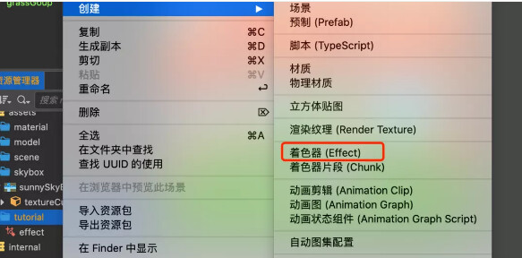
Create a new Cocos Creator 3.4 project, and in the assets directory, right-click the mouse and select Create Shader (Effect) in the popup menu. As shown in the following image.
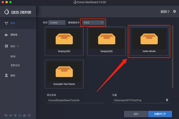
Quick Tip: When creating a new project, it is recommended to choose the
HelloWorldtemplate. This template providesstatic models, aCubemap, and other materials convenient for you to learn and use.
As shown in the figure below:
Step 2: Create a material and use the one you just created (Effect)
Create a material using the right-click menu.
Question: Are physical materials based on physics rendering?
Answer: No. Physical materials are materials used by the physics system to describe the physical properties of an object.
Select the newly created material, and in the Properties panel (Inspector) on the right, switch Effect to the one you just created. The following figure shows.
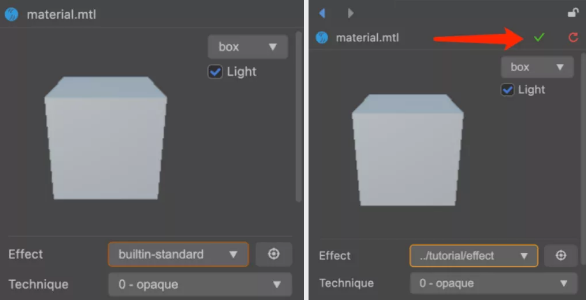
Quick Tips:
After switching, there will be a green tick in the material panel on the upper-right. Click to save the changes.
Step 3: Using 2D Textures
Dragging a 2D texture to the MainTexture parameter will reveal that the model in the material preview will change its appearance along with it.
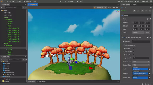
The DEMO in this article uses the shield texture that comes with the HelloWorld template project, as shown below:
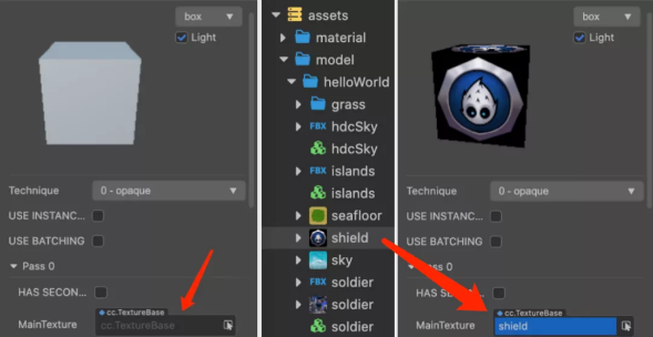
Shader analysis
If you read the shader(Effect) you just created carefully, you can see that a mainTexture property is defined in its properties area, which appears in the properties panel (Inspector). As shown in the following figure:
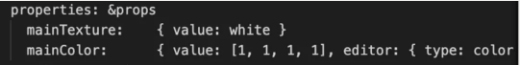
The default value of mainTexture is white, which means it will be white when not assigned a value.
In unlit-fs, the following statement can be found:
uniform sampler2D mainTexture.
It defines a uniform of type sampler2D.
This is the standard 2D texture property definition, and this mainTexture is a 2D texture.
In the frag function, the following statement can be found.
vec4 col = mainColor * texture(mainTexture,v_uv).
The texture function in this statement is used to get the texture’s pixel color value (RGBA) at the specified uv coordinate, which is what we call texture sampling. As shown in the following figure.
Some people may wonder, what is v_uv? Where did it come from?
This v_uv is the texture coordinate, which is passed to fs by vs.
You can check the contents of the general-vs.chunk in the next section of this article to see where v_uv comes from.
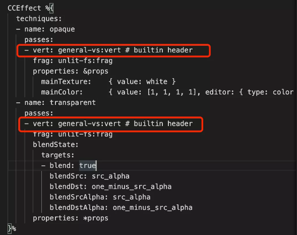
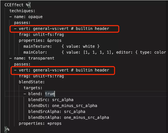
Others may be wondering why the new default Effect doesn’t have unlit-vs.
This is because, in most cases, there is no need to change the vs, so the Cocos Creator engine provides a built-in general-vs for you to use.
The path to general-vs is internal/chunks/general-vs.chunk.
The 'general-vs:vert #builtin headerin the newly createdshader (Effect)` references it. As shown in the following image.
If you want to customize vs it, just copy it over and modify it as needed.
To take care of those who “don’t have time,” I will show you the contents of general-vs.chunk.
precision highp float;
#include <input-standard>
#include <cc-global>
#include <cc-local-batch>
#include <input-standard>
#include <cc-fog-vs>
#include <cc-shadow-map-vs>
in vec4 a_color;
#if HAS_SECOND_UV
in vec2 a_texCoord1;
#endif
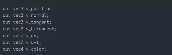
out vec3 v_position;
out vec3 v_normal;
out vec3 v_tangent;
out vec3 v_bitangent;
out vec2 v_uv;
out vec2 v_uv1;
out vec4 v_color;
vec4 vert () {
StandardVertInput In;
CCVertInput(In);
mat4 matWorld, matWorldIT;
CCGetWorldMatrixFull(matWorld, matWorldIT);
vec4 pos = matWorld * In.position;
v_position = pos.xyz;
v_normal = normalize((matWorldIT * vec4(In.normal, 0.0)).xyz);
v_tangent = normalize((matWorld * vec4(In.tangent.xyz, 0.0)).xyz);
v_bitangent = cross(v_normal, v_tangent) * In.tangent.w; // note the cross order
v_uv = a_texCoord;
#if HAS_SECOND_UV
v_uv1 = a_texCoord1;
#endif
v_color = a_color;
CC_TRANSFER_FOG(pos);
CC_TRANSFER_SHADOW(pos);
return cc_matProj * (cc_matView * matWorld) * In.position;
}
As you can see from the code in general-vs.chunk, this vs built into the engine does the calculations for tangent and bitangent by default.
Please remember to remove it based on performance concerns if you have projects that really don’t use it.
Also, it can be found that the default vs has an output for standard vertex information such as position, normal, uv, uv1, color, etc., which can be used directly in fs. As shown below.
3.3 Using smaplerCube in Cocos Shader
The smaplerCube corresponds to Cubemap (cube mapping), more aptly described as cube box mapping.
Imagine using 6 square 2D textures and stitching them into a hollow cube box to get a Cubemap.
For easier viewing, Cubemap is usually displayed as a six-sided spread. This is shown in the following figure.
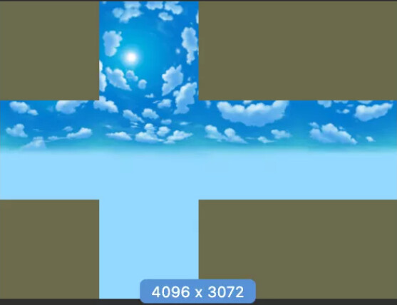
This feature is straightforward to remember. The next time you see a picture like this, you’ll easily recognize it.
Next, let’s take a look at Cocos Shader and how to use it with Cubemap.
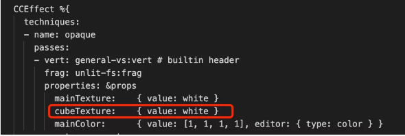
Step 1: Add a new cubeTexture property to properties
Create a shader (Effect) using the method described in the previous section.
Add a cubeTexture property below the mainTexture, as shown below.
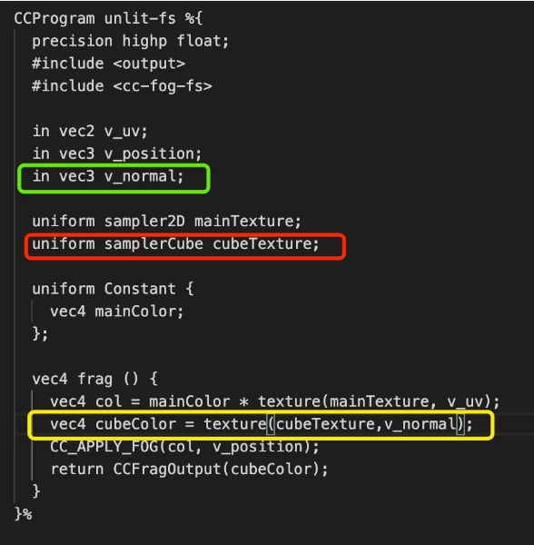
Step 2: Add a new uniform of type samplerCube to the unlit-fs
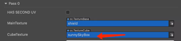
Below uniform sampler2D mainTexture, add uniform samplerCube cubeTexture. It should look similar to the red box in the figure below:

Step 3: Import normal data
We talked about how Cubemap is actually a hollow cube in the previous step. So how do we get information about it?
Suppose there is a huge cubemap box, and at some point in the box, a ray is emitted in a certain direction.
The ray will eventually form an intersection with the cubemap box, and the color value at the intersection is the color value we want.
It is easy to see that if you put an object into the environment, if you want the object’s surface to map the contents of the cubemap, the ray used must be inseparable from the face orientation of the object.
In the 3D rendering process, the information that determines the face orientation of an object is called the normal. Therefore, the normal information needs to be introduced first.
Since general-vs already outputs v_normal, it only needs to be introduced in unlit-fs to be used.
Add a line in the vec3 v_position; below, import vec3 v_normal; and use v_normal. See the green box marked below for an example.
Step 4: Sampling the Cubemap
The prototype of the Cubemap sampling function is vec4 texture(samperCube cubemap,vec3 coord).
Quick Tips: The texture function in Cocos Shader has many owners, and it will pick the appropriate function prototype based on the type of data passed in.
So use texture function for both 2D texture and Cube texture to pass in different parameters.
The final sampling function is marked in yellow in the figure below.
To test the effect, let’s create a new material.
Select the shader (Effect) you just wrote as Effect.
Drag assets/skybox/sunnySkyBox onto the CubeTexture parameter of the material, as shown in the image below.
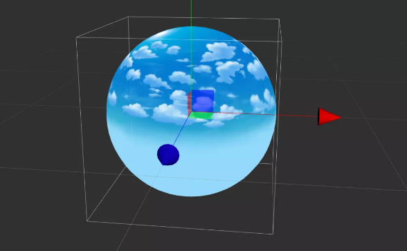
Create a new ball in the scene and use this material. The final effect is as follows:
Step 5: Correct Reflection Calculation
When you rotate the camera in the editor scene, you will find that the relationship between the skybox and the sphere is fixed.
In the real world, the content reflected by the object has nothing to do with the rotation of the object when the environment remains unchanged.
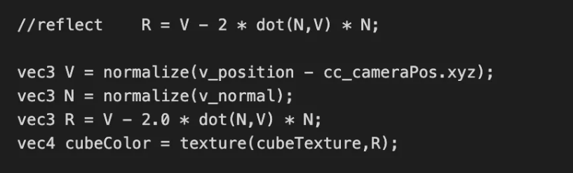
Commonly, Cubemap sampling is generally done using the direction of reflection of the line of sight based on the normal plane to sample.
Therefore, the reflection direction of the line of sight needs to be calculated based on normal and sampled using the reflection direction.
Let the view direction be V, the normal direction be N, and the reflection direction is R (V,N,R are all unit vectors).
The R derivation process is shown in the following figure:
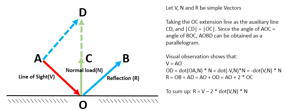
The final equation is R = V - 2*dot(V,N)*N
Based on the above formula, we modify the sampling of the CubeTexture in the shader as follows.
Without turning it, it’s hard to feel with v_normal the difference from using it directly for sampling.
But when we turn the camera, we can clearly perceive the changes brought about by the reflection.
If you replace the sphere with other irregular models, this feeling will be more obvious.
Step 6: Reflection Intensity Control
After completing step five, we can get a total reflective shader, but this shader is not very applicable.
Total reflection is very rare in the real world, so it is necessary to add factors that control the strength of reflection to make the reflection on the object’s surface more realistic.
First, in properties, add two properties:
• maskTexture is used to control the reflection strength of certain parts of the object’s surface.
• reflectionStrengthen is used to control the overall strength.
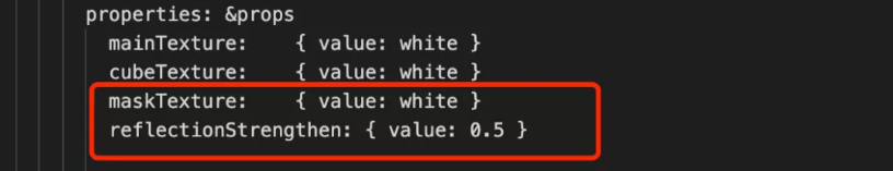
Then add the corresponding uniform, as shown below:

Finally, use the attribute you just added in the frag as follows.
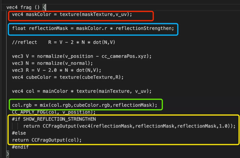
Code in the red box is for sampling maskTexture.
The code in the blue box will take the r channel of maskTexture as the reflection intensity factor and multiply it with the global intensity factor to get the final reflection factor.
Quick Tips:
The simple use of the
rchannel here is a very common practice formasktextures.rchannel is in effect even withsingle-channel texturesorgrayscale textures. Of course, it is also possible to use theg,b, orachannels or to calculate the reflection intensity by various formulas, depending on the situation.
The code in the green box is a linear interpolation between the background color and the reflection. When the reflection is stronger, the background color is weaker, and when the reflection is weaker, the background color is stronger.
The code in the yellow box will bring up a SHOW_REFECTION_STRENGTHEN switch in the material panel. Turn this switch on to view the reflection intensity.
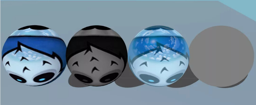
Four balls are rendered in the DEMO to demonstrate the effect, as shown in the following image:
-
The 1st ball uses the
shield mapas themaskTexture. You can see that the brighter the area, the greater the reflection intensity (like the coconut head), and the darker the area, the less the reflection intensity (like the blue part). -
The 2nd sphere shows the final reflection intensity of each part of the material from the 1st sphere. The overall darkness is because the global strength
reflectionStrengthenis set to0.5. -
The 3rd sphere is the case where the
maskTextureis empty. Since the default value ofmaskTextureiswhite, maskColor.r is always 1.0, i.e., full reflection. And thereflectionStrengthenis 0.5, so the primary color and the reflection are 50/50, and the reflection is the same in all parts. -
The 4th sphere is the final reflection strength of each part of the material shown for the 3rd sphere. The overall gray color is because the global strength
reflectionStrengthenis set to0.5.
Resources related to this section in the DEMO:
Effect: assets/tutorial/effect-cubemap.effect
Scene: assets/tutorial/tutorial-cubemap.scene
4. Texture properties
In the assets window, select any texture. In the Inspector property window, see the texture-related properties on the right. As shown below:

4.1 Texture sampling method
MinFilter, MagFilter, and MipFilter are the sampling methods that need attention in the figure below. They can effectively improve the rendering effect.
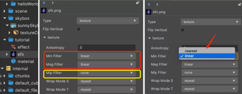
Their meanings are as follows:
MinFilter
- Downsampling - used when the texture resolution is larger than actually needed.
MagFilter
- Sampling while zooming in - for when texture resolution is smaller than actually needed.
MipFilter
- Mipmap sampling - used when getting pixel information from all levels of Mipmap when Mipmap is on.
However, the concept of light is still difficult to understand. Next, we will use an example to let you understand their functions in detail.
The figure below:
-
Picture 1- normal viewing angle -
Picture 2- Camera zoom out -
Picture 3- Camera zoom-in view.
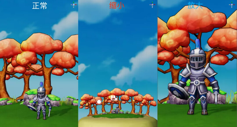
Now that everyone focuses their attention on the characters, it is obvious that in picture 2, characters in the middle have become smaller, and picture 3 characters in the middle have become larger.
However, the roles of picture 2 and picture 3 use the same texture.
That is to say, the same texture area is displayed in different sizes on the screen.
If the character texture size is 512x512, picture 1 is its best viewing angle.
Then Picture 2, since the proportion of the screen occupied by the texture is reduced, to ensure a better effect, a downsampling process needs to be done when the texture is sampled.
In picture 3, the proportion of the screen that the texture occupies becomes larger, and the sampling processing needs to be enlarged when the texture is sampled.
4.2 Texture filtering method
There are two types of texture filtering
• Nearest point filter (nearest)
• Linear filtering (linear).
Nearest point filtering selects the nearest pixel to use. As shown below:
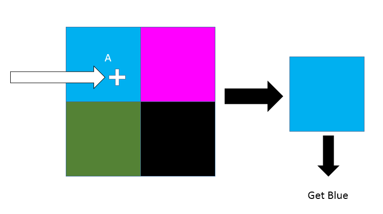
Nearest point filtering
You can think of a texture as a grid composed of pixels. When sampling, which grid the uv coordinates fall into, and which grid is taken.
The advantage of nearest-point filtered sampling is that it has good performance and no additional operations.
But there are both gains and losses. The disadvantage of filtering sampling at the nearest point is that the effect is not good whether it is zoomed in or zoomed out.
Linear filtering selects the pixel area of the nearest pixel 2x2 to perform weighted blending.
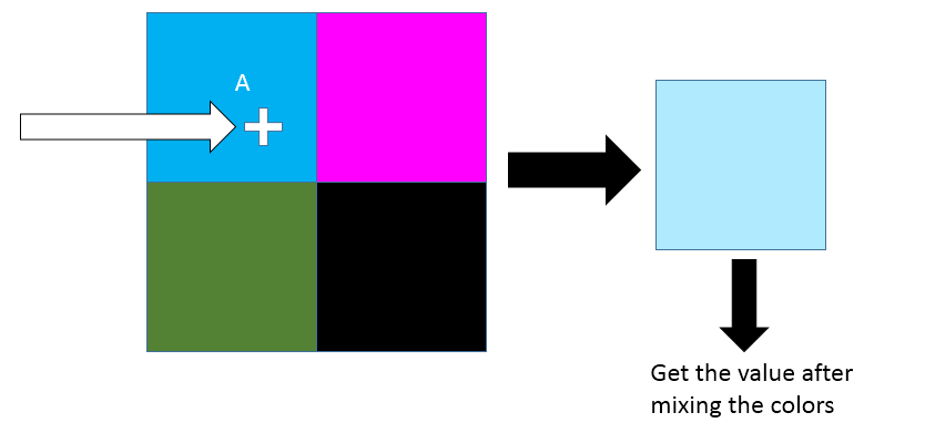
Linear filtering
The advantages and disadvantages of linear filtering compared to nearest point filtering are just the opposite: linear filtering is more effective but has lower performance.
Quick Tips:
Although linear filtering has a little lower performance than nearest point filtering, linear filtering is used in most cases since nearest point filtering is not satisfying the visual requirements in many cases.

Comparison of two filtering methods (the picture comes from the Internet)
Quick Tip:
The above image is only for texture upsampling and downsampling, i.e.,
MinFilterandMagFilter.MipmapSee below for sampling filtering.
Given the existence of MinFilter and MagFilter, what is the point of Mipmap?
It’s embarrassing to say that the main reason for Mipmap's appearance is that narrowing down the filter sampling doesn’t work well.
MinFilter can work fine when there is not much narrowing.
But when the reduction reaches a certain percentage, MinFilter can’t do anything.
Pixels that have shrunk too much won’t change due to ‘squeezing.’
On the other hand, Mipmap avoids the pixel ‘squeeze’ problem by generating small resolution textures step by step with a preemptively better filter sampling algorithm.
The following figure compares the effect of Mipmap filtering with None, Nearest, and Linear, respectively.
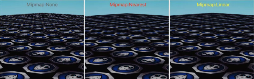
As you can see in the above figure, the near pixels are acceptable whether Mipmap is on or not. This is because the near pixels are not squeezed.
-
When Mipmap Filter is None, Mipmap is not turned on.
-
When Mipmap Filter is Nearest, the closest Mipmap layer is selected first.
-
When Mipmap Filter is Linear, the two close Mipmap layers are selected, and linear interpolation is done.
Quick Tips:
Textures generally used for 2D Sprite do not have Mipmap turned on, and textures used for 3D model rendering need to have Mipmap turned on.
4.3 Texture addressing mode
The texture addressing method, mainly for uv coordinates greater than 1.0, provides the appropriate addressing strategy. The Cocos Creator engine provides the following three texture addressing modes:
-
repeat
- Parts greater than 1.0 are modulo divided, leaving only the fractional part.
-
edge constraint ( clamp-to-edge)
-
Take 0.0 when it is less than 0.0.
-
Take 1.0 when it is greater than 1.0.
-
-
mirror repeat ( mirrored-repeat)
-
When the integer part is even, take the fractional part.
-
When the integer part is odd, subtract the fractional part from 1.0.
-
The effect of the three texture addressing is shown in the following figure:
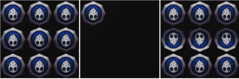
Left: repeat, middle: clamp-to-edge, right: mirrored-repeat
Quick Tips:
When you need a large area of floor tiles, glass windows, and other repetitive effects. Use
REPEATmode and adjustuvtiling. You can effectively reduce the texture resolution and save video memory.
clamp-to-edgecan ensure clean edges.
mirrored-repeatis a specialrepeat, not many occasions to use, can be used as needed.
3D texturedefault torepeat.
repeaton some low-end APIs (e.g.,WebGL 1.0) requires a texture size ofpower 2. So,3D modelrendering usespower 2textures whenever possible to enhance compatibility.
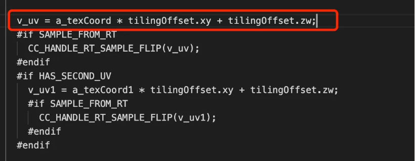
Here is a supplementary description of addressing-related properties on a standard material TilingOffset, as shown in the following figure:

TilingOffset on material panel
TilingOffset As the name suggests, it is responsible for adjusting the Tiling (scaling) and offset of the uv.
Where the xy component is used to adjust the Tiling, the value of xy will be multiplied with the uv, making the uv value larger or smaller.
Setting them to 3, as shown above, will be repeated 3 times in REPEAT mode.
The zw component is used to adjust offset. The value of zw will be added to the uv, making the uv value offset.
As shown below, the exact formula can be seen in internal/effects/builtin-standard.
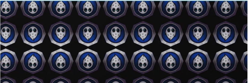
The following figure is the effect of x=10, y=10, z=0.3, w=0.3.
Maybe some serious developers will ask: In Cocos Creator, how to modify the addressing method of a texture?
If a texture is used for a 3D model, the properties window (Inspector) on the right will show the texture-related properties after selecting a texture in assets.
Just change Wrap Mode S and Wrap Mode T in the properties window.
This S and T are what we often call UVs, as shown in the following figure.

Some developers may ask, What is the relationship between UV and ST?
-
In
UVWspace,Uindicates horizontal direction,Vindicates vertical direction, andWindicates depth direction (actually, there are3Dtextures in addition to2DandCubetextures. (They are just less used and not expanded on in this article.) -
UVWis a coordinate for uniform textures and is widely used in the3Dmodeling field. -
In
STQspace,Sdenotes horizontal direction,Tdenotes vertical direction,Qdenotes depth direction. -
STQcan represent non-uniform texture coordinates, andSTQcan be used in cases where texture perspective correction needs to be handled. Therefore, in texture-related fields,STQis widely used. -
U=S/Q,V=T/Q. Therefore, whenQ=1.0(i.e., no perspective correction is needed),UV=ST. -
UVW,STQ, and the three components ofXYZall representhorizontal,vertical, anddepthin the orthogonal coordinate system, respectively. It is only in different fields that different letters are used to denote the concepts for better differentiation.
Quick Tips:
If you want to modify the
textureaddressing method of thesprite, expand the resource content of thespritein theassetswindow and check thetexturein thespritecontent.
5. Common effect achieved
5.1 Texture UV flow animation
Finally, it’s time to start moving the Shader from static to dynamic.
One small step on the Shader, one big step on the effect.
Quick Tips:
One prerequisite for texture
UV flowanimation is that the texture addressing method isREPEATormirrored-repeat.
In the animation above, the left one is repeat, and the right one is mirrored-repeat. You can see the difference in the orientation of the Cocos Logo head.
The principle of texture UV flow is very simple. When sampling the texture, you need to add a time-dependent offset to the uv. This is shown in the following image:
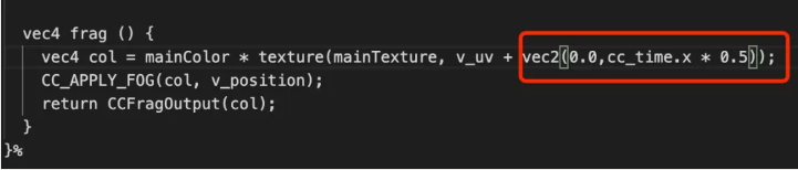
Where cc_time is a built-in Shader variable provided by the engine, and the x component represents the time elapsed since the start of the project. The yzw component is not used for now.
More built-in variables can be found directly in: Official Engine Documentation -> Graphics Rendering -> Material System -> Builtin Shader Uniforms.
Quick Tips:
Press the left and right mouse buttons simultaneously in the editor window to view
texture flow effectswithin theCocos Creatoreditor. For laptops without a mouse, justlong-pressthe touchpad.
5.2 Texture UV switching animation
An image like the one above should be no stranger to most people; it’s a 2-row, 4-column texture atlas.
There are two ways to implement texture UV switching animations:
-
Method 1 calculates the corresponding texture coordinates in
TypeScriptand then modifies thexyandzwparameters of theTilingOffsetproperty in the material. -
Method 2 calculates the corresponding texture coordinates directly in the Shader.

For a 2-row, 4-column texture atlas, it is easy to determine that each submap occupies a proportion of the UV. Each submap occupies 0.25 horizontally and 0.5 vertically, so setting TilingOffset's x to 0.25 and y to 0.5 is sufficient.
For this texture atlas, it is also easy to figure out the offset parameters for all subgraphs:
First row: [0.0,0.0], [0.25,0.0], [0.5,0.0], [0.75,0.0]
Second row: [0.0,0.5],[0.25,0.5],[0.5,0.5],[0.75,0.5]
Setting row=2, col=4, we get.
-
The percentage of each subgraph in the horizontal direction is
1.0 / col(i.e.,0.25). -
The percentage of each subgraph in the vertical direction is
1.0 / row(i.e.,0.5).
The formula is :
-
z = (index % col) * 1.0 / col
-
w = floor(index / col) * 1.0 / row
You can bring in the check.
Create a new script and write the corresponding code with the above formula. This can be done using the previous tutorial in this series so that I won’t go over it here.
Let’s implement the Shader-based texture UV switching effect step by step.
Step 1: Create a new shader (Effect)
Refer to step 2 in 3.1 of this article and create a new shader named: effect-texture-anim.effect.
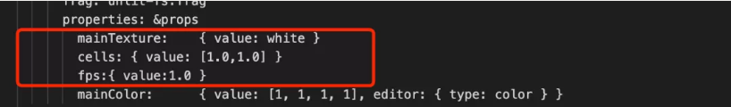
Step 2: Add properties in properties
In the properties area, add two properties:
-
cells: typevec2, used to mark the number of horizontal and vertical subgraphs in the texture map set. -
fps: type isfloat, used to control the speed of submap switching.
Step 3: Add Uniforms
In unlit-fs, add two uniform, as shown in the following image:
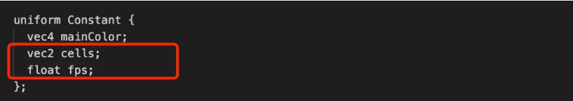
Step 4: According to the above formula, write the shader
vec4 frag () {
   float index = floor(cc_time.x * fps);

   float row = cells.x;
   float col = cells.y;

   vec2 offset = vec2(mod(index,col)/col,floor(index/col)/row);
   vec4 color = mainColor * texture(mainTexture, v_uv / cells.yx + offset);

   float gray = color.r * 0.299 + color.g * 0.587 + color.b * 0.114;
   color.a = gray;

   CC_APPLY_FOG(color, v_position);
   return CCFragOutput(color);
 }
Step 5: Create a new material and use this shader
Create a Plane or Quad in the scene.
Create a new material, use this Effect, and set the corresponding texture parameters to end up with the following effect:
Resources related to this section in the DEMO:
Effect: assets/tutorial/effect-texture-anim.effect
Scene: assets/tutorial/tutorial-anim.scene
5.3 Multi-texture blending
Multi-texture blending is a very frequently used point in Shader writing.
Common application scenarios are multi-layer ground blending, object surface detail, flow effects, dissipation effects, skeleton effects, petrification effects, etc.
The implementation of multi-texture blending in the Shader requires only three steps.
Step 1: Add the necessary texture parameters
This can be changed based on the previous shader (Effect), or a new one can be created.
First, add a texture property to the properties
Then unlit-fs add the corresponding sampler2D

Step 2: Fetch all the texture pixel values that need to be involved.
This is so simple, as simple as normal texture sampling. As shown in the figure below.

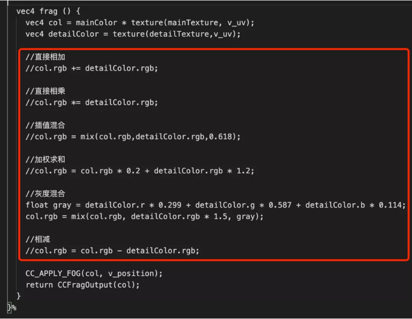
Step 3: Mix as desired
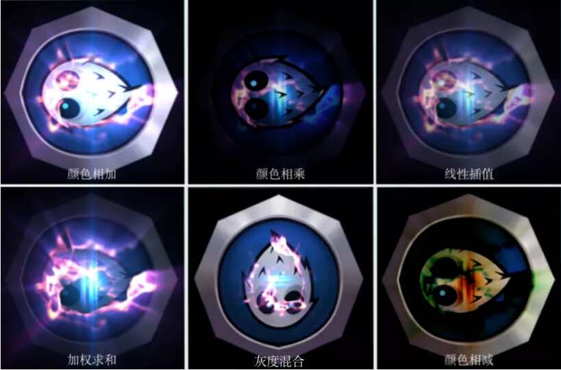
Formulas are free to make, but there are some quick-to-use formulas for common effects. As shown below:
The corresponding rendering results are shown in the following figure:
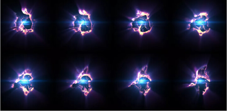
When combined with the UV switch animation, the effect at the beginning of the article can be rendered as follows:
Resources related to this section in the DEMO:
Effect:assets/tutorial/effect-texture-anim-blending.effect
Scene:assets/tutorial/tutorial-anim-blending.scene
5.4 Texture disturbance effect
The core idea of the texture scrambling effect is to interfere with the uv before the texture is sampled.
Interference is typically done by using another texture as the interfering texture.
The surface is definitely combined with the texture animation to visually see the scrambling effect.
Next, we implement two texture scrambling effects based on UV flow animation and UV switching animation, respectively.
5.4.1 Perturbation effect based on texture UV flow
The perturbation effect based on texture flow, the effect is as follows:
Perturbation effect based on texture flow
To achieve the above, the following functions need to be implemented:
-
Interfere with the sampling of the base map using an interferogram
-
Interference map UV flow
-
Control of interference intensity
-
Scaling of the interference map when blending with the base map
Next, I need to write out some code.
Step 1: Create a new shader (Effect)
Name this shader file: effect-texture-move-distortion (or you can name it as you like).
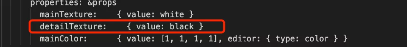
Step 2: Add parameters in properties:

-
detailTextureDetail map, which also acts as a perturbation map here -
strengthenDisturbance Strength Control Factor -
speedTexture UV flow speed,vec2is used here, is used to adjustuandvflow speed -
detailColorFactorThe blending ratio of the detail image when it is superimposed on the original image
Step 3: Add the relevant uniform to the unlit-fs
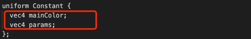
No mistake, only a uniform called params has been added here.
Please note that when adding properties such as strengthen, an additional target has been added more than before.
The significance of the target is redirection, which determines which components of which uniform are used for the property.
It can also be interpreted the other way around: target allows us to give the uniform components an alias in the properties panel, making it easier to understand the meaning of each component.
For example, in this example:
-
The alias for
params.xisstrengthen -
params.yzis aliased tospeed -
The alias of
params.w isdetailColorFactor
Quick Tips :
The main reason this mechanism occurs is becauseuniformtakes up memory space.And different platforms, when compiling
shader, have different rules foruniformmemory layout, which may cause memory wastage.So it is recommended that when you write
Shader,uniformtry to be mainlyvec4.
Step 4: Let the interference map flow
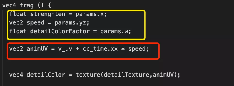
The part marked in yellow is to facilitate the writing of the Shader. We use several temporary variables to store the params’ components according to the properties’ definitions.
The red box marks the part that does a time-dependent offset of the uv. This was covered in the texture UV flow animation earlier in this article and will not be covered again.
The final detailColor sampled is a texture that keeps flowing.
Step 5: Disturbance Processing
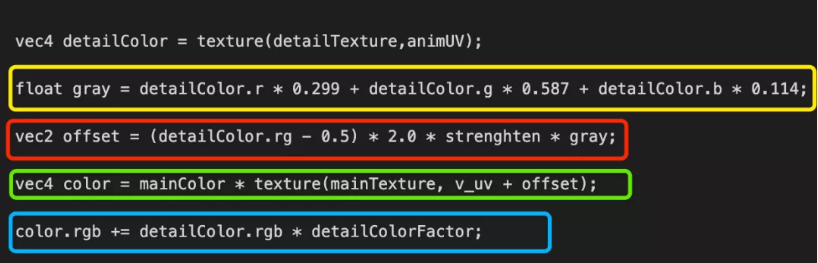
Grayscale calculation
In the above figure, the statement marked by the yellow box:
float gray = detailColor.r * 0.299 + detailColor.g * 0.587 + detailColor.b * 0.114
Since the detail image used in this example does not have an ALPHA channel, the grayscale formula is used here to calculate the grayscale value of the image that is used to participate in the intensity operation.
In the case of pictures with ALPHA channels, the ALPHA channel values are used directly.
You can also simply use detailColor.r as a perturbation intensity to calculate.
Quick Tips:
When it is
gray, you should find that some people use itgray, and some people use itgrey.
Don’t worry. Both are fine, whatever the pronunciation.
offset calculation
Pay attention to the code marked in the red box in the figure above, as shown below:
vec2 offset = (detailColor.rg - 0.5) * 2.0 * strengthen * gray
Here the rg channel is used as the uv perturbation factor, but the r and g are values in an [0.0,1.0] interval.
If you want to perturb uv within a range, rather than deflect in a particular direction, the desired perturbation factor needs to be in an interval of [-1.0,1.0].
Let’s recall the content of high school mathematics together:
- If
f(x)the range of the function is[0.0,1.0]. - set
g(x)=(f(x) - 0.5) * 2.0. - The available
g(x)value ranges are[-1.0,1.0].
Finally, we can get one x, the offset of the y component in the interval [-1.0,1.0].
Intensity control
At the end of the equation, * strengthen * gray, this controls the intensity of the disturbance.
-
Strengthenis the overall scaling of the offset, which is used to adjust the disturbance intensity as a whole. -
Grayis the intensity control of individual pixels, resulting in a ripple effect.
Sampling and Mixing
With the previous preparations, you only need to mainTexturesample the
offsets involved. As follows:
vec4 color = mainColor * texture( mainTexture, v_uv + offset );
If we only do this step, we will find that the pixel will be disturbed by an invisible thing, as follows:
Whether it is a game, animation, or a movie, the special effects with spatial disturbance have more or less some color. So we also need to superimpose the color of the perturbation effect on the basemap. The code is as follows:
color.rgb += detailColor.rgb * detailColorFactor;
Which detailColorFactor is used to control the strength of the unique effect map display. The final effect looks like this:
Resources related to this section in the DEMO:
Effect: assets/tutorial/effect-texture-move-distortion.effect
Scene: assets/tutorial/tutorial-move-distortion.scene
5.4.2 Perturbation effect based on texture UV switching
The perturbation effect based on texture UV switching animation is much like the perturbation effect based on UV flow in the previous section. The essence of the difference is the detailTexture movement way problem.
The UV switching animation to be implemented in this section only needs to change the UV flow animation part, to UV switching animation.
Next, we talk about the differences.
Difference 1: properties
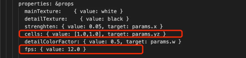
-
Speedis replaced bycells, which is used to mark the number of subgraphs in the set -
Added
fpsto control the switching frequency of subgraphs
Difference 2: uniforms
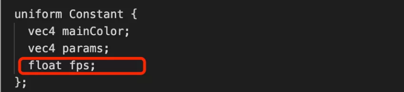
fps is a new property, and all 4 components of params are used up, so only a new uniform can be added to fps.
Difference three: animUV

animUV calculation method is replaced by the UV switching method.
The rest is the same as the previous subsection, and the final effect is as follows:
Resources related to this section in the DEMO:
Effect: assets/tutorial/effect-texture-anim-distortion.effect
Scene: assets/tutorial/tutorial-anim-distortion.scene
6. A 3D character effect surrounded by energy
The above effect can be achieved through the Shader combination in this article. Just edit the material parameters.
Resources related to this section in the DEMO :
Scene: assets/tutorial/tutorial-soldier.scene
7. End
Phew~~~, finally finished! I thought it was a simple introductory article, but it turned out to be more and more content. Time to stop!
The DEMO source code of this article can be obtained in the Cocos Store for free at the following address:
https://store.cocos.com/app/detail/3521
8. Other articles in this series
All articles are in Chinese
Cocos Shader Basics 1: Preface
Cocos Shader Basics 2: Getting to know Cocos Shader for the first time
Cocos Shader Basics 3: programmable pipeline analysis and Hello World
Cocos Shader Basics 4: Uniform and Material Parameter Control