
In the previous article, we introduced the process of building scenes in Cocos Creator with zero code. Some of you have given feedback that you have encountered some problems when building scenes and are unfamiliar with some of the terms and concepts in 3D assets. Today we bring you this “troubleshooting” article, where we will look at the various myths you may encounter when using 3D assets in Cocos Creator and hopefully help you solve the multiple problems you may have and have not experienced.
Developers who know game development know that art developers make 3D art assets in a DCC. Therefore, after moving to the engine stage, the first thing we need to do is the proper export and import of 3D assets, which includes the format used to transfer 3D models between DCC and the engine, as well as the data necessary for the assets to be used in the engine. During the model-building process, the art developers will take care of the data related to the 3D mesh. Still, suppose we don’t understand what data is essential and why it is important, even if we have a model asset with all the details ready for us. In that case, we will inevitably encounter all kinds of problems during the import process into the engine.
Anchor Points
All 3D models are built as individual mesh objects, each with its own Pivot Point (or Anchor Point). Anchor points are the axis points for all movements, rotations, and scaling of a mesh object.
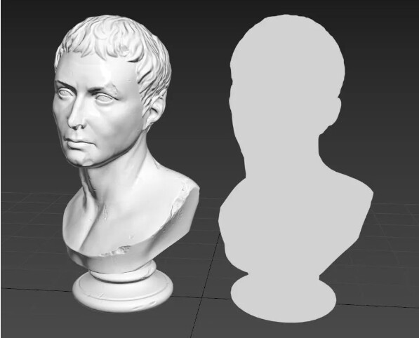
How do we know where the model’s anchor points are? One of the easiest ways to identify it is when you use the move, rotate, and scale tools, the location where the tool’s action handles appear on the model in the 3D viewport is where the model’s anchor point is located. Usually, after the model is completed, the art developer will place the anchor point in the center of the model or in the location that makes the most sense for the model. For example, a sculpture placed on the ground will usually have its anchor point in the bottom’s center. After all, for a statue, all movement, rotation, and scale changes are typically relative to the ground.

Moving the Model / Moving the Anchor Point
After the anchor points are placed, the art usually moves the model to the world origin (X, Y, and Z axes all take on the value of 0 in world space coordinates), which is why most 3D models open up and appear squarely in the center of the DCC viewport. This is not something that DCC will do for you when you open the model, but rather something that the art will do for the developers who follow the workflow during the model creation process. The first step in the process of rendering a 3D model is to convert the vertex position data of the 3D model into world space. Normalizing the vertex positions to the world origin saves a lot of trouble later. Of course, on the other hand, models are not only allowed to be exported and imported if they are located squarely at the world origin. They can be exported if they are anywhere in world space coordinates. If you export a model and cannot find it in the scene after importing it into the engine, you first need to determine whether the model was placed at the world origin when it was exported.
We have mentioned that the anchor points of the model should be placed at the center of the model or in the most logical position of the model. So, can the model be exported if the anchor points are not placed in these positions? Of course, the answer is no. If the anchor points are not placed in a suitable position, say a few meters away from the model, all of the movement, rotation, and scaling (often referred to as “transform”) operations on the model after importing into the engine will be centered on this few meters away position. Even if you don’t use the tools provided by the engine and use scripts to modify the model’s move, rotate, and scale properties programmatically, this problem will still exist. This is true for all engines, not just Cocos Creator.
The position of the model anchor point determines the axis of the model transformation
So, we don’t just brainlessly place all model anchors at their centers, and the problem is solved? The answer is also no. Sometimes we deliberately place anchor points at specific locations in the model, which will help us achieve the animation effect. As a typical example, we often see doors that can be opened in game scenes with a 3D model of the door panel embedded in a door frame. If the anchor point of the door panel is in the center of the door panel, then no matter how it rotates, it will only be stuck in the center of the door frame, and the “door” will not open at all. On the contrary, if we move the anchor point to the side of the door frame and let the door panel take the edge of the door frame as the axis, then a simple rotation animation can achieve the effect of opening the door.
Hierarchy
In 3D models, different mesh objects can also have hierarchical relationships. Unlike inheritance in code, the child layers of a 3D model do not inherit any other parameters from the parent except for the transformation parameters. For example, if you set the rotation parameter of the parent model to 90 degrees, and then set the same axial rotation parameter of the child model to 45 degrees, the final angle of the child model is 135 degrees. The child model inherits the 90-degree rotation of the parent model and then rotates itself by 45 degrees. Afterward, giving a material to the parent’s model, the child’s material does not change: the parent’s material is not inherited by the child. They still use their own material parameters.
Simply put: When we transform the parent, the child will move, rotate and scale with the parent as if it were “stuck” to the parent. Conversely, when we transform the child level alone, the model of the parent level does not change at all. This law of hierarchy is also the basic principle of the skeletal system implementation.
That said, this does not mean that when we use a model with a hierarchical relationship, we must bind bones to it. Or the example of the door panel and the door frame: after moving the anchor point of the door panel to a suitable position, we can put the door panel on the sub-level of the door frame so that we only need to move the door frame and the door panel will follow while the door frame does not change when the door panel is rotated and opened. To extend this further, we can add another wall model and put the door frame on the sub-level of the wall so that we can get a wall with doors facing various directions by simply changing the level of the wall, and the doors on the wall can also be opened. To extend this further, we can put the wall under the sub-level of the whole house model so that if we place the entire house anywhere in the scene, the walls in the house will face the right direction, and all the doors in the wall will open correctly.
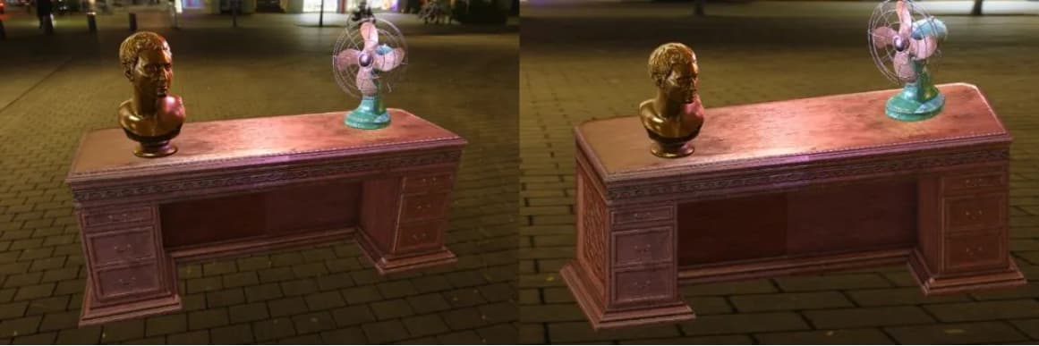
Let’s take another example: we have a model of an electric fan, and we want the fan blades to rotate and the fan head to swing from side to side as it does in everyday life. First, we can separate the fan blade from the fan model and place the anchor point at the point where the fan blade meets the fan head; then, we can separate the part of the fan head that can be rotated and place it at the point where it meets the rest of the fan. The fan blade will oscillate from side to side with the fan head while rotating on its own, so place the fan head on the sub-level of the remaining fan model and the fan head on the sub-level. Add keyframes to the rotation parameter of the fan blade so that it animates the rotation while the fan head and the remaining part of the fan are not affected; then add keyframes to the rotation parameter of the fan head so that the fan head can oscillate left and right, and the fan blade will be carried left and right by the fan head while rotating on its own. In contrast, the remaining part of the fan remains unchanged.
This method of using the basic relationship between parent and child hierarchy to get the transformation effect is called Forward Kinematics. You will find that we don’t need bones when using Forward Kinematics to create animation. Just simple anchor points and hierarchy relationships can achieve the effects you are looking to build.
UV
UV is one of the most important pieces of data a 3D model contains, as it directly determines whether or not the model can be mapped correctly. A model without correct UV data will not project any mapping on its surface accurately, and naturally, it will not be able to use any materials and shader effects correctly. Art developers will build their models with UVs accordingly.
UV is a set of 2D coordinate data, which can be understood intuitively as: the surface of a 3D model is cut into individual blocks, each block is flattened on the 2D plane, and all blocks are placed in the same mapping space so that the 2D data is the model’s UV. Because each UV block looks like an island on a map, these UV blocks are also called UV islands. Therefore, the critical element in handling UVs, besides how to cut them, is how to place the cut blocks in the 2D space of a map. The programmer probably does not need to care about how to use these. But in terms of use, the placement of UVs raises two questions: first, whether the independent UV blocks will overlap with each other; second, where precisely should the UV blocks be placed.
When two UV blocks overlap, it means that the same part of the texture is projected on their corresponding models, which is desirable in some cases: after all, it is not abrupt to have the same material and texture on the same model, and the fact that two UV blocks have empty space means that the remaining UV blocks have more room to use, and each UV block can project more map pixels, thus improving the accuracy of the material. Overlap is not always intentional and can be problematic for other purposes, such as rendering static maps. Static lighting mapping is rendering lighting effects as maps for use in a scene. It is almost impossible to have identical light and dark effects in different places on a model, so UV overlap is not allowed when baking static lighting maps.
As for the placement of UVs, most shaders only sample from the [0, 1] range in the 2D space of the UVs’ X and Y axes, so UV blocks are usually placed in a square grid with both X and Y axes less than 1. This grid is also called UDIM. Similarly, there is an infinite number of squares on the Y-axis, such as (1, 2), (1, 3), (1, 4), etc. Therefore, for clarity, we call the square closest to the origin of the coordinate system of UDIM1001 (1, 1).
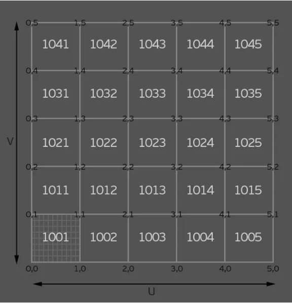
Although UDIM1001 is the space for UV placement in most cases since the shader can change the size of the mapping projection by scaling the UV value, there is no requirement for UV placement if the mapping used is quadratic, i.e., the top, bottom, left, and right sides of the mapping are seamlessly integrated: no matter where it is placed and the geometry of the UV block, it will achieve the correct effect no matter where it is placed and the geometry of the UV block.
In Cocos Creator, we need two sets of UVs for the model. The first set of UVs is used for materials and mapping, which, as mentioned above, can be handled flexibly according to the mapping and material requirements, regardless of whether they overlap or exceed UDIM1001, as long as the corresponding mapping is reasonable. The second set of UVs is only used for baking static lighting maps in Cocos Creator, and as we mentioned above, overlapping of UV blocks is not allowed and must be placed within UDIM1001.
Exporting
Once the model is ready in DCC, the next step is to export it from DCC in a staging file format for import into Cocos Creator. 3D models come in various formats, such as FBX and OBJ, commonly used in game engines, 3DS from the ancient DOS era, alembic from Industrial Light and Magic, OpenGL by Khronos, Collada, and so on. In Cocos Creator, we can only import models in FBX format. Note that FBX doesn’t only export models. It can also export cameras, lights, materials, maps, animations, etc. In the modeling stage, we only need to export the model.
Once the format is determined, we also need to pay attention to the model’s coordinate system. Two systems are used in computer graphics: the left-handed coordinate system and the right-handed coordinate system, corresponding to DirectX and OpenGL. These are the most common in graphics APIs. Cocos Creator uses the right-handed coordinate system, which is marked by the vertical upward axis as the Y-axis, and during the export process, we need to export with the Y-axis upward setting. Suppose your model is imported into the engine and still “falls” to one side (rotated by 90 degrees) even though the rotation parameter is 0. In that case, there is a good chance that the coordinate system was not chosen correctly for the export.
Vertex normals
In addition to anchor points and UVs, we may need to pay attention to the vertex normal data of the model. It is used to express the orientation of the model’s surface and, therefore, directly affects the gradient of the model’s surface. If your model looks “unclean” with strange light and shadow gradients, and if you can see geometry traces, then the vertex normals are usually the problem.
Although vertex normals are an essential piece of data for a model, in DCC, we don’t usually deal with them directly; DCC usually chooses to adjust them by wrapping them in another data set. For example, in 3ds max, vertex normals are defined using the “smooth group” feature, and in Maya, they are defined using the “soft and hard edges” feature. Although these functions have nothing to do with vertex normals, they modify the model’s vertex normal data. This is why, when models are transferred to each other in 3ds max and Maya, the effects of the models are the same, but the “smooth group” and “hard and soft edges” data are not inherited from each other. Because the final result of “smooth group” and “hard and soft edge” are vertex normal data, vertex normal data can be transferred between different platforms through the model file, but “smooth group” and “hard and soft edge” are not 3ds max and Maya-specific data and features, respectively.
Sometimes you may encounter models that look “blank”: they render only the outer edges in DCC, and the structure of the model itself is a solid block of color with no bump, even when given a new material and a different renderer. As we mentioned earlier, the vertex normal mainly affects the light-shadow gradient relationship of the model, so it is possible to use it to create a flat color with no light-shadow gradient at all. The only difference is that all vertex normal vectors are averaged in the same direction. This is ideal for models that use unlit materials and hand-painted maps. It completely eliminates any gradation of light and shadow due to the structure of the model and removes any gradation of light and shadow caused by too few faces or unreasonable wiring. So, what if we want to restore the normal vertex to normal for such a model? Most DCCs provide the ability to reset the vertex normals, simply by calling the appropriate function before exporting the model.
Types of models
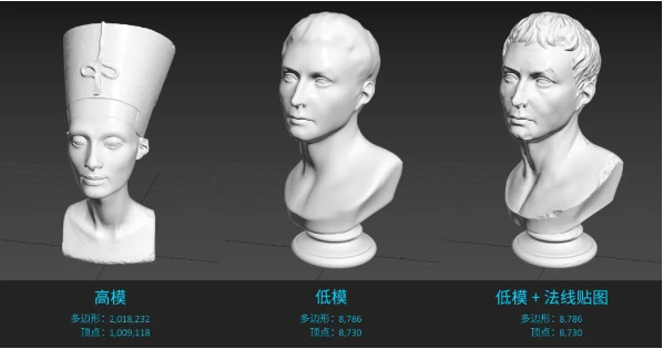
There are different ways to build models, but polygonal models are the most common ones we see in games. This type of model has a stable structure, precise data, and efficient execution. You may also know about NURBS models that are built using mathematical operations, SDF models that are formed using raymarching, and so on. In addition, we often come across the difference between high and low poly models. In short, a high-poly models is a model with a high number of vertices and polygons, which can be in the tens or even millions of vertices and polygons. The number of vertices and polygons determines how accurate the model can be in terms of detail, so a high-poly model can present a vibrant and realistic geometric structure, which is achieved by real vertices. The lighting algorithm can process each detail to create a realistic lighting effect. The high-poly mode requires high rendering power of the hardware at runtime and can run at very low frame rates without strong hardware support.
Similarly, a low-poly model is a model with a low number of vertices and polygons, which can have only a few hundred or even a few dozen vertices and polygon structures. Because of its simple structure, it will inevitably have an angular form. Accordingly, it runs very efficiently and can cope well with even older hardware. However, since it has a simple structure, it cannot express rich geometric details. If we use low-poly models alone, we can usually only represent simpler or “cartoony” objects and structures.
To solve this problem, we usually make a similar high die based on the shape of the low die, to which we can add various surface details, and then store the vertex normal data of the high die as a map, which is given to the low die through the shader. Although the model’s accuracy with normal mapping does not actually increase, the normal mapping can visually allow the low model to present rich details, thus kicking off the “next generation” that we often hear about.
Whether it’s a high-poly model, a low-poly model, or a “blank” vertex normal model, they can all be imported into Cocos Creator via FBX to serve various scenes and projects. The type of model you use depends on your project requirements.
Finally, it’s important to note that while there is essentially only a difference in the number of vertices and polygons between the high- and low-poly models, you can’t simply delete vertices and polygons from the high-poly model to get a low-poly model. The critical data of a model is not just structure and form, and we have already spent a lot of time on the role of vertex normals and UVs and their importance. Removing vertices is a very dangerous practice for models and will almost certainly lead to a mess of vertex normal and UV data. Don’t try it unless you know exactly what you’re doing.
Importing
After exporting the model, we can say goodbye to the DCC, and the next step is to import the model into Cocos Creator. The next step is to import the model into Cocos Creator. This is as simple as dragging and dropping the FBX file from its folder into the Explorer window of Cocos Creator.
After successful import, the FBX file will appear as a resource in Explorer. Click on it to view the model’s properties in the Properties inspector on the right. The properties here are directly related to the FBX we imported, so in most cases, we don’t need to pay too much attention to them.
As we mentioned earlier, in addition to models, FBX can also export materials and maps. The textures used for materials are encapsulated in the FBX and cannot be accessed as separate assets. Exporting materials and textures together through the FBX does not simplify your workflow. It may make a simple process more cumbersome, but if this cannot be avoided, for example, if a customer provides the model, the texture wrapped in the FBX can be found in a sub-level under Model Assets in the Explorer.
After importing the model, the model only becomes a resource added to our project directory. To use the model, we still need to drag and drop the model assets from the Explorer to the scene editor, adding the model to the current scene.
You may ask: “Why can’t the model automatically appear in the scene when I import Cocos Creator?” Because you may have more than one scene in a project, and the same model can be used more than once. Whether it’s a scene, a model, a material, a texture, or a script and code, they are all separate modules that serve the whole project. They may cross-reference each other to populate their own data as we see fit, but there is no mysterious code that binds them in a natural “one-to-one” correspondence in the background, out of our sight.
Once a model is added to the scene, you can see the model’s hierarchy in the scene in the hierarchy manager in the top left corner. Similarly, all nodes in the scene (or, in layman’s terms: everything that exists in the scene, regardless of what it does) are listed in the hierarchy manager. Thus, even a node that is not visible in the scene editor can be clicked in the hierarchy manager as long as it is present in the scene. Similarly, the hierarchical relationships we assigned to the model during the preparation of the model will also appear in the hierarchy manager as sub-levels of the model hierarchy.
Now that the model exists in the current scene, all we need now is to move it to the location we need in the scene. Using the Move, Rotate and Scale tools in the upper left corner of the scene editor, we can freely determine the position, orientation, and stretch of the model in the scene. Note that the model in the scene is an instance of our imported FBX, so no matter how we toss the model in the scene, it will not have any effect on the imported FBX. The model is just a module that serves the current scene, and all the changes we make to it, whether it’s moving its position, modifying its materials, or giving it different scripts, are all for the needs of the current scene. The new instance will be in the same state as when we first exported it from DCC, and will not change because of the changes we made to the previous instance.
The first data to be considered “3D” and, of course, the position in 3D space. Every node in the scene has its position, rotation, and scaling parameters, even an empty node without any function. So, when we use the model move, render and scale tools, we are actually modifying the model nodes’ position, rotation, and scaling parameters. Since this is the case, manually entering the corresponding values on these parameters will give precisely the same effect.
Camera
In addition to the model, we can also add new nodes to the scene. Clicking on the plus button in the upper left corner of the hierarchy manager shows a list of different nodes that can be added to the scene. These nodes are parameterized with spatial coordinates, i.e., they all have parameters for position, rotation, and scaling, and we can place them in the scene using the move, rotate and scale tools just like the model.
In addition, other functional modules in the engine, such as particles, Billboard, collision bodies, etc., although they are also closely related to the scene, cannot create their own 3D nodes directly. We must create a new empty node first and then add the corresponding functional modules to the empty node as components. Afterward, we can move the empty node to determine the placement and position of the corresponding component in 3D space. The null node can also be used as a parent of the model, so we can select several instances of the model in the scene and place them all on the same null node’s child hierarchy. This is equivalent to merging these models into one group, and we only need to move the empty node of the parent level to treat these models as one model and perform the transformation together.
Among the 3D nodes with their own spatial coordinate parameters, one of the most important nodes is the camera. The camera is a proxy for the user’s viewpoint when running the scene. We can adjust the camera parameters to adjust the user’s view of the mirror image or add control scripts to the camera so that the user can freely control his position and viewing angle in the scene, ISO, and so on. In addition, we can also choose the projection mode of the camera. Although it is called “projection,” it has nothing to do with shadows. Its primary function is to modify the coordinate data of the vertices of the objects seen by the camera to form a perspective effect in the art (i.e., “near big and far small”). By taking its value, we can get an orthogonal view without perspective, which is also quite common in games.
Perspective view / Orthogonal view
A camera node is already created in the Cocos Creator scene by default. In addition, we can create a new camera in the scene by clicking the plus button in the top left corner of the hierarchy manager and selecting Camera.
We can also move, rotate and scale the camera. When moving the camera, we can see the view from the current camera perspective in the preview window in the bottom right corner of the scene editor, which can help us find an ideal camera angle.
After deciding on the camera angle, we can click the Play button in the top center of the scene editor to open a browser preview of our scene.
Materials
Although we have exported materials accordingly when we exported our model earlier, you can see that the instances of FBX assets imported in Cocos Creator do not have materials. The result is the same even if the texture is used for the material it packed when exporting the FBX. This is because the model uses DCC’s own shaders while rendering in Cocos Creator requires Cocos Creator’s shaders. Since there are so many popular DCCs on the market, different DCCs use different shaders, and different DCCs with different renderers will lead to more shaders, so it is challenging to recreate the DCC rendering in the engine perfectly.
We can check the FBX asset and check Dump Material under the Material tab in the Property Inspector. The engine will automatically assign a material based on the data and mapping (if any) already packed in the FBX. However, you will notice that even so, the rendering is still different from what we see in DCC. It’s true: the texture used by the material plays a crucial role in how the material behaves. But just by putting the texture where it belongs, the relationship between the material parameters and the different data in the texture is still not replicated. This is why we need to emphasize repeatedly: the model, material, and texture. These are all modules that help us achieve the effect. There is no necessary, natural, mysterious, and inexplicable connection between them. Therefore, we cannot mechanically move one module to another and hope to get the exact same effect.
Where can the model’s materials be viewed? We can select the model in the scene, and in the property inspector on the right side, we can find the Materials parameter and click on the arrow button to see a list of all the materials used by the model. We first have to create a new material asset to assign material to the model. A new material file can be created by clicking the plus button in the Explorer and selecting Create / Material.
Just as the model in the scene is an instance of the imported FBX, the material is also an instance of the shader it uses. The material allows us to assign values to the various parameters written in the shader. A texture is a representation of a value. After the texture is projected onto the model’s UV, it is equivalent to telling the shader what value to assign to each model’s pixel when rendering. This value can be a color or a simple number, and the different algorithms in the shader will calculate their own light output based on these numbers. Therefore, mapping is just a way to assign a value, and there is no mystery in itself.
Once the material settings are complete, click the checkmark button in the upper right corner to save the changes to the material file. Then, we just need to drag the material file we just saved into the Materials parameter of the model and overwrite the existing file in it.
With the model almost done, we can save our progress. Choose File / Save Scene or Save as in the top menu bar to save the current scene. The saved scene will also appear as an asset in the Explorer window. Double-click on the scene to open it.
Environment
In the previous section, we have already handled the conversion of the model from DCC to the engine. The next step we need to focus on is how the scene should be rendered inside the engine. The model is only there to serve our scene, and we are only halfway through the process once the model is taken care of.
Anyone who knows 3D workflow knows that the 3D space, as understood by the computer, is just a bunch of coordinate data in a Cartesian coordinate system, in which there is no sky, no earth, no objects, not even light. To make this space rich, you must make all the corresponding things. Although DCC can help model everything in the world, it is still too time-consuming to model every scene, starting from the sun, moon, and stars. So, we use a real-life HDRI map to wrap our 3D scene. Like a background in a painting, the HDRI map will present us with the parts of the world that must exist but are not very relevant to our scene. This allows us to focus our attention on the representation of our subject.
So, is it necessary to have HDRI mapping in the scene? The answer, of course, is no. Again: all modules are for our scene, and we can certainly choose to discard some of them at the cost of missing content and functionality, but if the missing part happens to be irrelevant to our desired effect, then there is no harm in doing so.
Our scene has a model, but the surroundings are still blank. We can start by giving the scene a large background. Here we need an HDRI map. In Cocos Creator, we can only use HDRI mapping in HDR format. If your mapping is in EXR format, just do a quick dump in Photoshop, and it will import correctly.
As with the model, we can import the HDRI mapping by simply dragging and dropping the HDR file into the Explorer window.
To use the HDRI map we just imported in our scene, we just need to select the root layer in the layer manager and then, under the Skybox tab in the properties inspector, drag the HDRI map onto the ENV Map parameter, making sure that Enabled is checked. Otherwise, the HDRI map will only be displayed in the editor and not at runtime.
Compared to before, our scene already has a rough feel. Under the Ambient tab, we can adjust the exposure of the HDRI mapping. We can also adjust the color of the sky diffuse and ground reflections, which have been automatically generated for us based on the HDRI mapping. However, we can also set our own colors if we feel that the model and background are still not blending well enough.
Light
We mentioned earlier: what is not created in 3D space does not exist, and the same is true for light. If no light source is created, everything in 3D space is invisible. No matter how complex the model is and how advanced the shader is, all we can see is pitch black. In Cocos Creator, adding HDRI mapping enables sky diffuse reflection and ground reflection, so we don’t have pitch black in our scene. However, to really see our scene clearly, we also need to add light sources.
Cocos Creator adds a directional light to the scene by default. As with other nodes, we can manipulate its position, rotation, and scaling and modify its property parameters in the property viewer.
Cocos Creator has three types of lights: directional light, sphere light, and spotlight.
We have repeatedly introduced these three common light sources. So is there a difference in the light source for indoor scenes compared to outdoor scenes?
-
Directional light: Directional light works similarly to natural sunlight, but that doesn’t mean that directional light can only be used as sunlight or that directional light doesn’t need to appear in a cloudy and rainy scene. You can use directional light for any directional pointing and the need to spread throughout the scene of light sources. In addition, since directional lights can illuminate the entire scene indiscriminately, directional lights can also be used as a lighting “bottom” for the entire scene." For example, indoor scenes at night, whether or not there are other sources of light, you can use a directional light, giving a lower intensity and cooler, darker colors for the whole scene to lay the tone of the night sky light.
-
Spherical lights: Spherical lights have no directional pointing and can only illuminate a certain range. This makes them ideal for lighting specific areas or creating large gradations of light and dark. Whether indoor or outdoor, spherical lights are suitable. But because there is no specific direction, spherical lights are very unsuitable for producing projections. Even if the general lighting effect has been established, it is possible to add a few more spherical lights in a targeted manner, to add more light intensity differences, or “gradient” differences, to the existing light.
-
Spotlight: Spotlight is mainly used when a projection is needed or when there is a clear range of illumination. The effect of a spotlight is more focused on the illuminated part, and the part that is illuminated is easily lacking, so you can add a sphere light to the spotlight light source, and the two can work together to get a more natural effect.
Shadows
Shadows and lighting are usually accompanied by the existence of, after all, no shadows; we can hardly feel the presence of light. Shadows can accompany lighting, calculated on-the-fly at each rendering frame, or the shadows can be baked into a texture and superimposed on the material as a map. The former obtains shadows that are updated at every frame and can be accompanied by dynamic light sources to form dynamic shadows but consumes additional rendering resources. The shadows of the latter are already baked as a texture and cannot be updated in every frame. Still, they can significantly improve the rendering efficiency at runtime with little sacrifice of screen effects. In Cocos Creator, we can turn on dynamic shadows for light sources or apply the engine’s built-in baker to bake static shadow maps.
To turn on dynamic shadows in a scene, you need to set up the environment, the model, and the light source separately.
First is the model, select the layer where the model mesh is located in the layer manager, and under the Dynamic Shadow Settings tab, set the Shadow Casting Mode to on.
Next is the light source, select the light source and check Shadow Enabled under the Dynamic Shadow Settings tab.
Finally, for the environment, select the root level of the scene in the Hierarchy Manager and check Enabled under the Shadows tab.
There are two types of dynamic shadows in Cocos Creator, which can be selected in the Type parameter of the Shadows tab.
Planar is a simple shadow type that can only be cast in the direction facing the X, Y, and Z axes. If the object receiving the shadow is uneven or rotated at an angle, the shadow will pass through the mold. Related settings include Shadow Color, which determines the color of the shadow, and the Normal parameter, which determines the direction of the plane of projection.
Shadow Map is a more detailed type of shadow that can be cast onto any surface of the model. Obtaining the desired shadow effect requires a combination of several parameters.
First, select the scene root level and adjust the Shadow Map Size under the Shadows tab to make sure there are enough pixels to draw the shadows. If shadows are not visible in the scene, or if they are in several rectangular shapes, then this is the first parameter to be adjusted.
Next, select the light source, and under the Dynamic Shadow Settings tab, choose Shadow Pcf as Soft 2X or Soft 4X. The Shadow Map will form jagged edges by default, and adjusting this setting will enable the relevant blurring algorithm to soften the edges of the shadows that are too sharp.
Again, select the light source and adjust the value of Shadow Distance under the Dynamic Shadow Settings tab to get satisfactory shadow details. Size to save performance.
Finally, adjust the value of Shadow Saturation, which is equivalent to the semi-transparency of the shadow.
Baking
Static Light Map takes the light and shadows of the current scene and bakes them onto several maps based on the second set of UVs of all models, then overlays the maps onto the materials to render the light and shadow effects through the color output of the materials. After baking static lighting maps, the light and shadow relationships in the scene will no longer be influenced by the light source. The light-shadow relationships will be rendered entirely by the baked mapping. The material and environment parameters can still be accessed and modified as usual. Still, if the light source parameters are modified, the lighting in the scene will no longer match the results of the static lighting map baking, so the static lighting map will need to be re-baked.
Cocos Creator’s baking static lighting requires separate settings for the environment, model, light source, and material.
First is the model, select the layer where the model mesh is located in the layer manager, and under the Lightmap Settings tab, check Bakeable, Cast Shadow, and Receive Shadow.
-
The purpose of Bakeable is to allow the object to join the queue for baking. If not set, the model will continue to use dynamic lighting.
-
Cast Shadow is a switch for whether or not the model casts shadows.
-
Receive Shadow is a switch for the model to allow projections from other models to be cast on itself.
-
Lightmap Size determines the size of the map baked by the model, and we will expand on the values of this parameter later.
Next is the light source. Select any light source and check Bakeable and Cast Shadow under the Static Settings tab.
Then the environment, select the root level of the scene in the level manager, and check Enabled under the Shadows tab. This operation is the same as dynamic shadows, of course, if you do not want to generate shadows in the scene, you can skip this setting.
Lastly, for materials, select the material used in the scene in the Explorer and tap Use Second UV.
Once the settings are complete, select Project / Lightmap in the menu bar at the top of the editor to open the Baker window.
Most of the parameters here do not need to be modified by us. The ones we need to pay attention to are
-
MSAA: This will affect the accuracy of the baking result and, at the same time, will significantly increase the calculation time needed for baking. Increasing this value can solve the quality problems such as blurred and dirty baking.
-
Resolution: As the name implies, this determines the resolution of the baked mapping.
-
AO Color: The default color is too light, and the result of baking may not be obvious enough. When baking for the first time, you can directly choose pure black and choose a different color according to the adjustment needs.
After setting, click Lightmap Generate and select the output path of baking in the pop-up dialog box (the assets folder under the default project directory can be used) to start baking.
After the baking is done, we can see the preview of the baked static lightmap in the Baked tab of the baker.
We can see that the static lighting maps are baked separately at different sizes based on the model’s second set of UVs, and then integrated into the same map.
If we open the baked static lightmap, its size is 1024 × 1024, and compare the Resolution value of 1024 in the baker, we will find that the baker will draw the baked static light to a map with the resolution of the resolution value of the baker according to the size of the Lightmap Size of the model. If the Lightmap Size of the model is exactly equal to the Resolution of the baker, then the baker will bake a separate map for the model. If the Lightmap Size of the model is smaller than the resolution of the baker, then the static light baked by the model will only take up part of the map. The rest will be reserved for the static light maps of other models. The remaining amount will be reserved for the static lighting maps of other models.
Thus, we can conclude that the Lightmap Size parameter of the model must be smaller than the Resolution parameter of the baker, and it is better to have a POT value (64, 128, 256, 512, etc.) to ensure the baking effect while maximizing the space of each static light map.
After the static lighting is baked, the light and dark relationships will be superimposed on each material in the form of a texture. Even if we modify the material, it will not affect the baked static lighting maps. Only when we modify the light source color, intensity, direction, and other parameters do we need to rebake the static lighting.
When we don’t need static lighting and need to return to the unbaked state of dynamic lighting, we can go back to the Baker panel and click Lightmap Clear under the Baked tab.
When we have baked static lighting but found that the scene is too bright or too dark, you need to re-adjust the parameters of the light source, and the light source is modified, then you need to rebake the light. This can take a lot of time to adjust the light parameters and repeat the baking. We finally see the scene of the degree of light and dark, not only by the light source to determine. The camera will also affect the overall brightness of the scene.
When we are generally satisfied with the relationship between light and dark of the existing light sources and only need to fine-tune the overall intensity, you can select the camera, adjust the camera’s aperture, shutter, and ISO parameters, you can adjust the brightness of the scene without repeatedly baking static lighting.
Reflections
Now the basic elements of our scene are in place. We still need to turn on one last switch for the scene.
Although our model currently has materials, there is still something lacking in the performance of the materials. In particular, metals are still strange in our scene.
Back at the root level of the scene, select Diffuse Map with Reflection from the ENV Lighting Type dropdown menu under the Skybox tab.
This setting adds the ambient lighting influence of the scene to all materials, allowing the model and scene to blend more naturally.
In addition, clicking the Bake button for the Reflection Convolution parameter generates a reflection convolution map that will add reflection effects to all materials. The intensity of the reflection can be adjusted by the Roughness parameter of the material itself.
Note that both of these functions are based on the HDRI map we added to the scene, so if the ENV Map parameter is not assigned to the map or if the map itself is too simple and lacks detail, you will not get the appropriate effect.
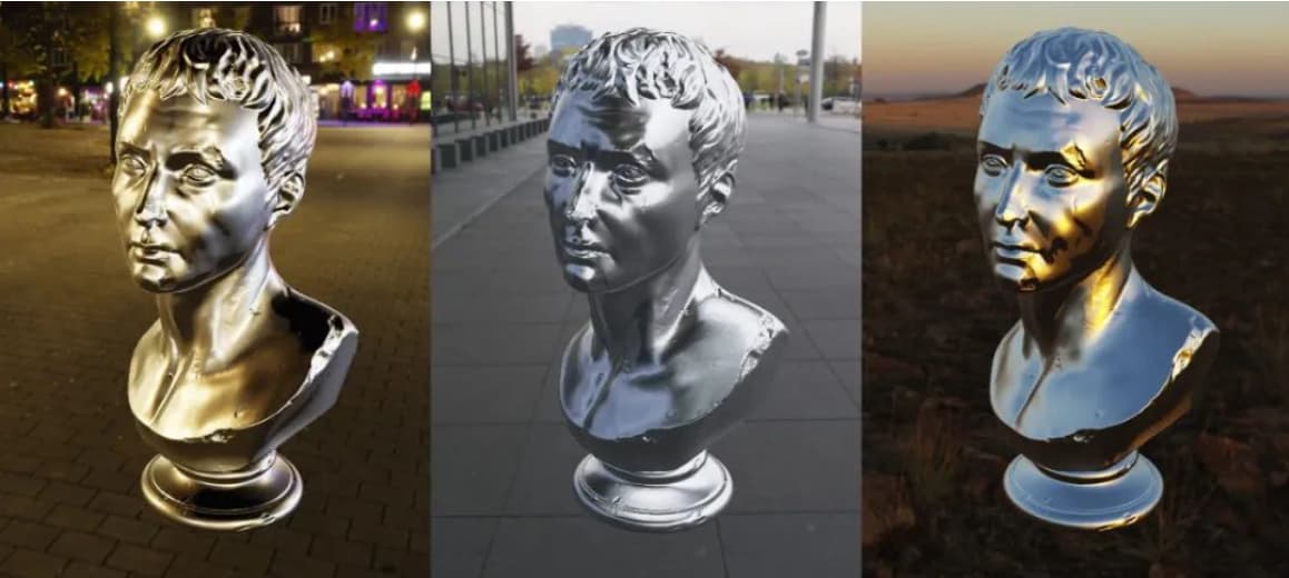
The HDRI map of the scene determines the reflection effect.
I believe that you will have a clearer and smoother experience when building your own scenes. I look forward to seeing everyone’s work.
In addition, the official Cocos sermon team is putting together a “Cocos Creator 3D Asset Inflow Guide” to give you a more comprehensive and in-depth understanding of how to use the engine’s 3D assets and build 3D assets efficiently. The material is expected to be available soon, so stay tuned!