
Building a 3D outdoor scene with zero code in Cocos Creator
For programmers that have been exposed to 3D game art resources, a monologue similar to this may have appeared in their minds:
-
How are these 3D models used, and why do I keep getting errors when importing them?
-
What are these images for? What’s the material?
-
Why is my scene dark? Why don’t the models in the scene have shadows? Why do things in the scene plummet after more than one frame rate?
-
I bought art resources online. Why is it uglier than what the sellers showed when I put them in my scene?
At the same time, for 3D artists who have been exposed to game engines, may have a monologue like this in their mind:
-
Why is my model so small in the engine, and the rendering looks so big?
-
Why are my scene colors so ugly? What kind of atmosphere do I want?
-
Why won’t the program let me use more textures? They say the framerate is too low?
-
Why, even if I put someone else’s model in my scene, the effect is not as good as someone else’s screenshot?
Today, we won’t talk about code, won’t write shaders, or do science. We will return to the starting point and create a 3D outdoor scene in Cocos Creator from a pure and new perspective. This article may be a bit long, but you what you will learn here is that you don’t need to be able to write code, you don’t need to be able to model and sculpt, you just need to remember to “click here and click there.”
This article will follow the essential operation:
-
Material
-
Environment
-
Directional light
-
Dynamic shadow
-
Other light sources
-
Static lighting
-
Model modularization
-
Material assignment
-
Baking configuration
-
Model placement
-
Lighting design
-
Others
Well, we now start with the basics of the basics.
Basic operation
When we open a newly created Cocos Creator project, the first interface we see usually looks like this. All the operations we will do next can be expanded into four primary workspaces: Resource Manager, Scene Editor, Property Inspector, and Hierarchy Manager:

First of all, we can import all kinds of art resources into the engine through the resource manager. Be it 3D models (.fbx, .gltf), pictures (.jpg, .png, .tga, .bmp, .hdr, .psd), audio (.mp3, .wav, .ogg, .m4a) or videos (.mp4) files. These can be directly dragged to the directory resource manager to import into the current assets directory of our project.
The
assetsdirectory resource manager is actually precisely the same as the directory structure in the /assets folder of the project on the hard disk. Therefore, copying and deleting the assets folder in the project directory on the hard disk is the same as the operations of importing, deleting, and updating under the resource manager.
Note: Although the following formats are also standard, they do not support direct import into Cocos Creator:
.obj, .tiff, .gif, .exr, .flac, .mov, .avi, DCC-specific storage formats such as .max, .ma, .mb, .blend, etc.
After the resources are imported, we can also create several new folders in the resource manager to quickly classify different types of resources. The resources that have been imported into Cocos Creator can be hot-updated. In other words: even if the resource has been used in the scene, you can change its directory location in the resource manager at any time; when necessary, you can make changes, then re-import the resource manager and all instances of the resource that have been used in the scene will also be updated with the second import.
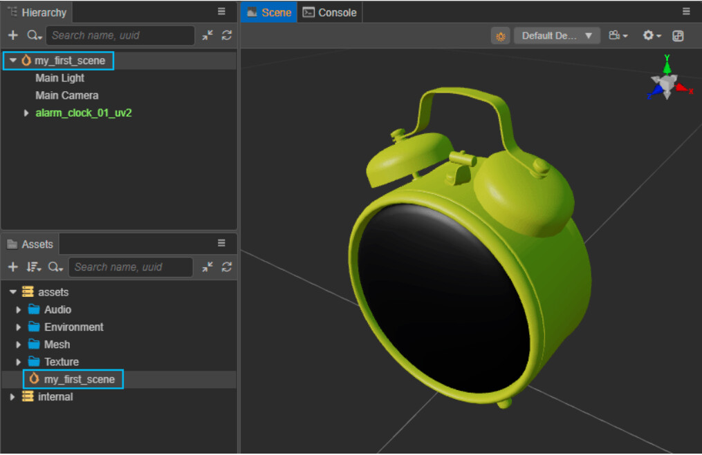
How are the imported resources used in the scene? We just need to select the imported 3D model file in the resource manager and drag it into the scene editor. What you will notice is models dragged into the scene immediately appear in the list in the hierarchy manager and are displayed in green. This indicates that the model has been added to the scene as a sub-level of the scene’s root level (named by default).
Why can’t I see the model when I drag it into the scene editor? This may be due to the relatively small size of the model itself. First, select the model in the hierarchy manager and press the shortcut key F to make the scene editor automatically focus on the selected model in the scene.
Let’s save our progress. Press the shortcut key Ctrl/Cmd + S, or select File → Save Scene in the menu bar to save the current scene in the /assets folder of the project directory. You will find that as the scene is stored as a separate file in the project directory, the scene also appears as an asset in the resource manager. Not only that, but the scene root level in the hierarchy manager is also updated with the name of the scene file.
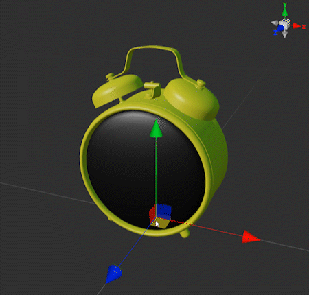
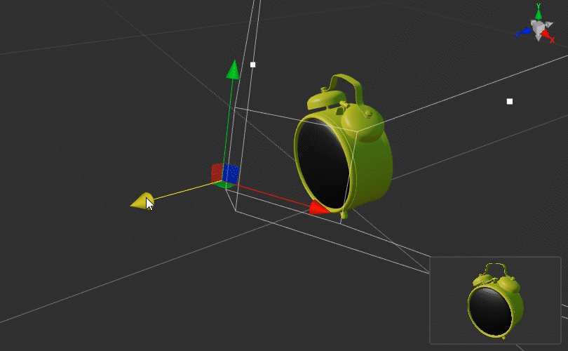
All 3D objects in the scene can perform the basic movement, rotation, and scaling operations, which can be achieved using the toolbar at the top left of the interface.
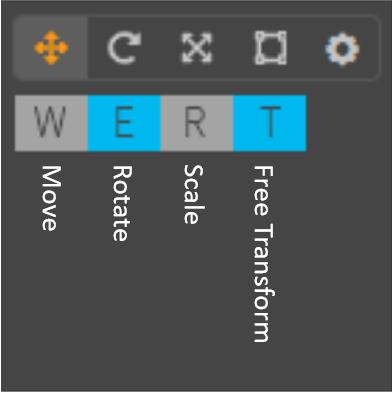
The tools in the toolbar are the same as for most DCCs. The shortcut keys W, E, R, and T correspond to the Move, Rotate, Scale, and Free Transform tools. After selecting a tool, use the corresponding deformer in the scene editor to displace, rotate, and scale the 3D object. At the same time, the object’s position, rotation, and size parameters are updated accordingly by the property inspector. You can directly input values in the parameters in the property inspector, and you can also complete the operations of displacement, rotation, and scaling.
The Free Transform tool is currently only available on 2D objects.
In Cocos Creator, the value of the parameter is automatically accurate to three decimal places, so there is no floating-point overflow problem. It is still a good practice to manually enter values that are closer to integers.
In addition to the model we dragged into the scene, the scene already comes with a directional light and a camera by default. Of course, we can also shift, rotate and scale them.
When operating the camera, we can see a preview window of the camera perspective in the lower right corner of the scene editor to help us get an ideal camera angle.
Let’s take a quick preview of what we’ve done so far. Click the play button above the scene editor. You can choose to preview the effect of the scene running in the browser or simulator.
In the browser, you can see some useful stats at runtime in the lower-left corner, including FPS, Draw Call, number of triangles, etc. At the top of the preview window, you can also adjust the preview window size, horizontal and vertical orientation, etc.
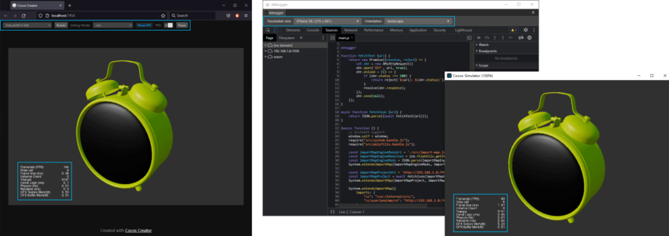
For scene construction, a browser preview is sufficient. However, this does not count as a real “Play on Device” test. What if I need to preview the running effect on my phone?
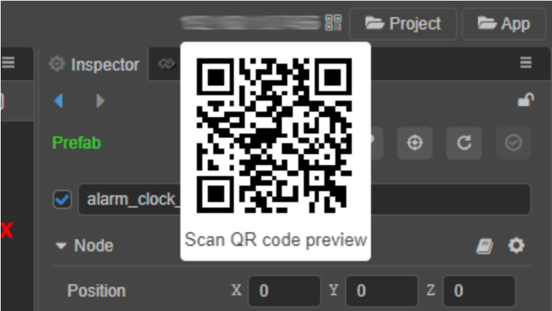
First, make sure the phone is connected to the same WiFi network as the platform we are developing. Above the property inspector, we can see a list of IP addresses. Hover over the IP address, and a QR barcode will appear.
During the development process, you can use your mobile phone to scan the QR code at the top right of the editor to preview your project on your phone.
Material
The model we imported has entered the scene, and a question has also arisen: why is it green? When we exported .fbx and .gltf, didn’t we already export the material as well?
The reason is actually straightforward: no matter which DCC the model is made in, its material must be based on one of the built-in shaders in that DCC. There are thousands of different DCCs on the market today, and there are countless shaders. Even if the PBR process is also used, there will be a difference between the left-handed coordinate system and the Metal/Roughness and Specular/Glossiness processes. Therefore, it is more challenging to seamlessly migrate a 3D material directly from DCC to any engine. When we export 3D assets, we export the model’s Material ID, and the default material file is automatically assigned based on the Material ID. In the engine, we need to assign a new material based on the engine’s shader according to the model’s Material ID.
In other words: the Material ID of the model is the key to assigning the material. In the process of the DCC making a model, as long as the Material ID is defined, make sure that no meshes with no defined Material ID are missed, even if the model is exported without assigning a material.
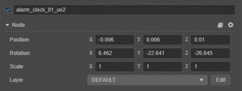
Expanding the model’s hierarchy in the hierarchy manager, we see that the model’s mesh data is stored in the 3D model’s prefab as a sublevel using the cc.MeshRenderer. The materials array parameter available under the cc.MeshRenderer module already contains a .material file.
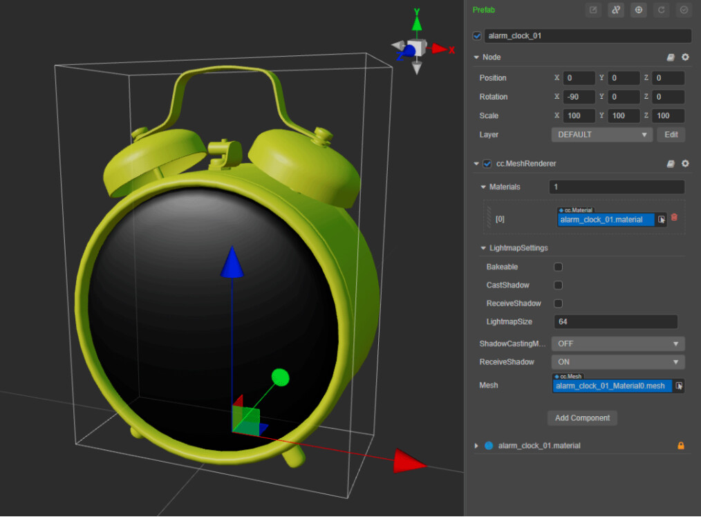
This .material file is why our model is green. This .material file is created with the model export, and its rendering function in DCC cannot be inherited in Cocos Creator. The Materials parameter is an array because a mesh can have multiple Material IDs, even if the materials that come with the mesh cannot be rendered correctly. As long as the Material ID data of the mesh remains unchanged, we only need to use the built-in materials in Cocos Creator and replace the material in the Materials parameter.
In the above figure, the Materials parameter contains only one .material file, indicating that the entire mesh has only one Material ID and can only be replaced with one material. Note: Material IDs and mesh faces are one-to-one correspondence. Although you can change the number of Material IDs by manually modifying the Materials parameter in Cocos Creator, this modification will not affect without defining the corresponding mesh. Changes to Material IDs must be made in your DCC.
Next, we just need to replace the .material file with the material file in Cocos Creator.
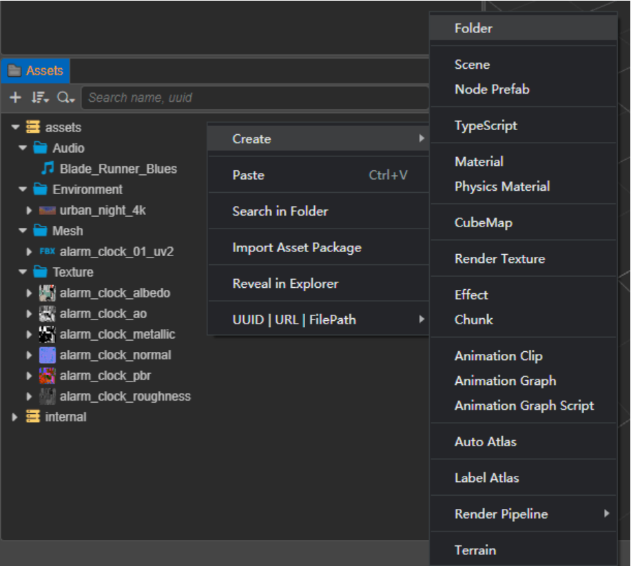
First, we click the plus button in the upper left of the resource manager or right-click any blank area of the resource manager, select Create → Material, and create an empty material file.
Note: Material files in Cocos Creator are in .mtl format, not .material.
Select the new material, and you can see the parameters of the current material in the property inspector. First, select the shader used by the material in the drop-down menu of the Effect parameter.

By default, the newly created material uses the built-in PBR Shader in Cocos Creator. Its usage is straightforward: check the options for Normal, Albedo, and PBR maps, and assign the maps to the corresponding parameters.
In addition, we also need to check USE LIGHTMAP and USE SECOND UV. Although these two parameters have nothing to do with the effect of the material, their importance will be reflected later.
The PBR texture in the default PBR Shader in Cocos Creator refers to the AO, Roughness, and Metallic surfaces in the Metal/Roughness process, which are stored in one texture with red, green, and blue channels, respectively. Please refer to the relevant documentation for more details on using the shader.
After adjusting the shader parameters, click the green checkmark button in the upper right corner of the property inspector to save the changes to the material. After that, go back to the mesh of the model level in the level manager, assign the new material to the materials parameter, replace the existing .material file, and complete the assignment of the material.
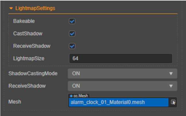
Before we finish processing the model, first check the Bakeable, CastShadow, ReceiveShadow options under the LightmapSettings tab and set ShadowCastingMode to ON. The purpose of this operation will discuss in detail later.
Environment
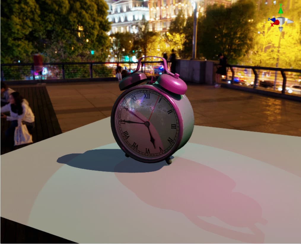
We have successfully imported the model into the scene of Cocos Creator and used the shader in Cocos Creator to achieve the performance of the material effect, but this is still not enough. After all, a solitary 3D model stands in the scene, surrounded by an endless vacuum, which is miles away from how we usually understand the scene. Therefore, we need to prepare a more natural environment as a macro background for the scene.
Of course, we don’t need to use the model to realize all the distant mountains, near water, sun, moon, and stars in the background: such planning is not scientific, and the scene in the background does not need to be presented complicatedly. So, using environmental panorama mapping becomes the best choice.
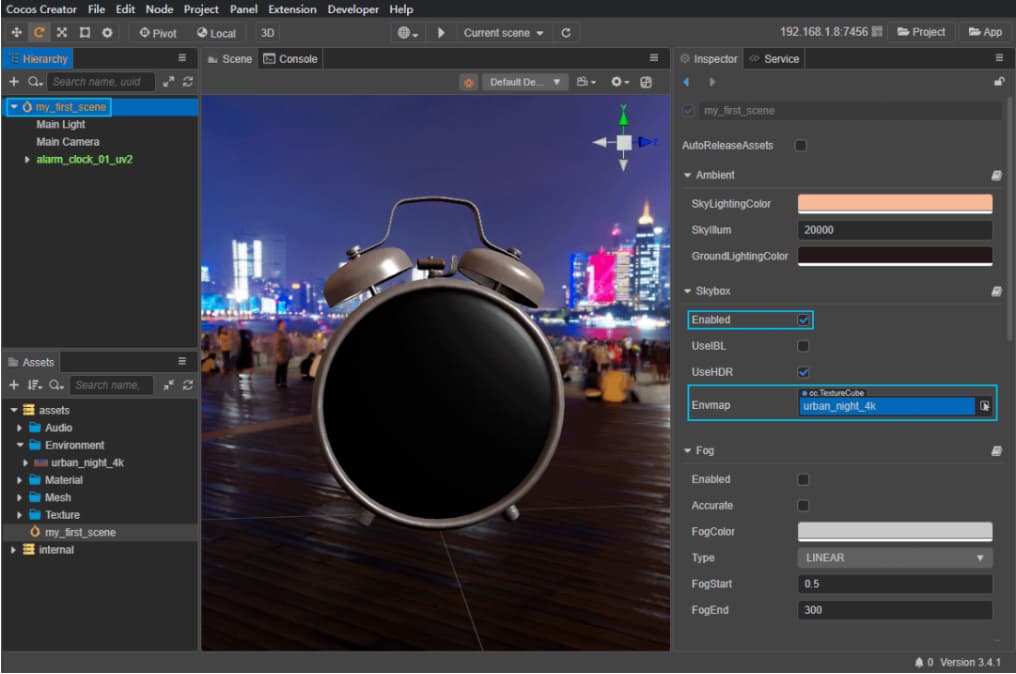
First, we import the panorama map (.hdr) into the engine through the resource manager. Select the imported resource in the resource manager, and you can view the corresponding property parameters in the property inspector. Because of the 360-degree projection method of the panorama map, the Type parameter is set to texture cube. In addition, because the color data in .hdr format is stored in linear color space, we use the Is RGBE parameter. In general, these settings are done automatically when the texture is imported.
So, how to use panorama maps? Select the root level of the scene in the hierarchy manager, and the property Inspector will display the scene’s environment property parameters accordingly. Drag the panorama texture resource to the Envmap parameter and set it to Enabled.
With Environment Maps enabled, you will notice that the SkyLightingColor and GroundLightingColor have changed. These two parameters represent the diffuse sky color and the ground reflection color. The so-called diffuse reflection of the sky refers to the color that particles and dust in the air indirectly produce lighting effects on the environment by reflecting sunlight. In art, it can be simply understood as the color that the bright part of the object should appear when there is no sunlight outdoors during the day. Ground reflection refers to the color of the light in the environment after it is reflected on the ground. In art, it can be simply understood as the color that the dark part of the object in the environment should appear. Therefore, the relationship between these two parameters is somewhat similar to the relationship between high-key and low-key in color matching. Their cooperation will determine the overall color performance of the object receiving light.
The engine will automatically choose the sky diffuse color and ground reflectance color according to the brightness of the environment map. However, this option is not necessarily what we need. The easiest way to use these two parameters is to match the colors in the environment map: SkyLightingColor adjusts to a color similar to the sky color in the map, and GroundLightingColor adjusts to a color similar to the ground color. The third parameter in the middle SkyIllum controls the panorama mapping exposure and affects the intensity of SkyLightingColor and GroundLightingColor. There is no standard value for this parameter. We can decide according to our own needs. This is because the .hdr map contains global exposure range data. There will be no underexposure or overexposure of ordinary images, so it needs to be stored in a linear color space.
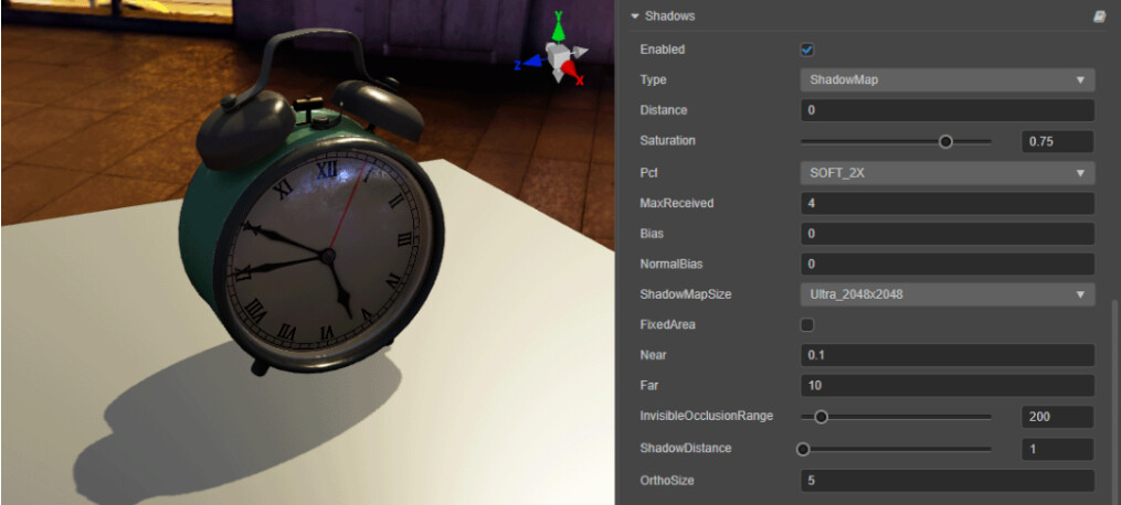
Before processing the environment, we also need to open the Shadows tab in the property inspector, check Enabled, select Type as ShadowMap, select SOFT_2X for Pcf, and select ShadowMapSize as the maximum value ( Ultra_2048x2048 ). The purpose of this operation will be revealed below.
Finally, to render the environment map at runtime, we also need to select the camera in the hierarchy manager and SKYBOX in the clearFlags Parameters under the cc_Camera Modules. Otherwise, our environment map will only be visible in the editor.
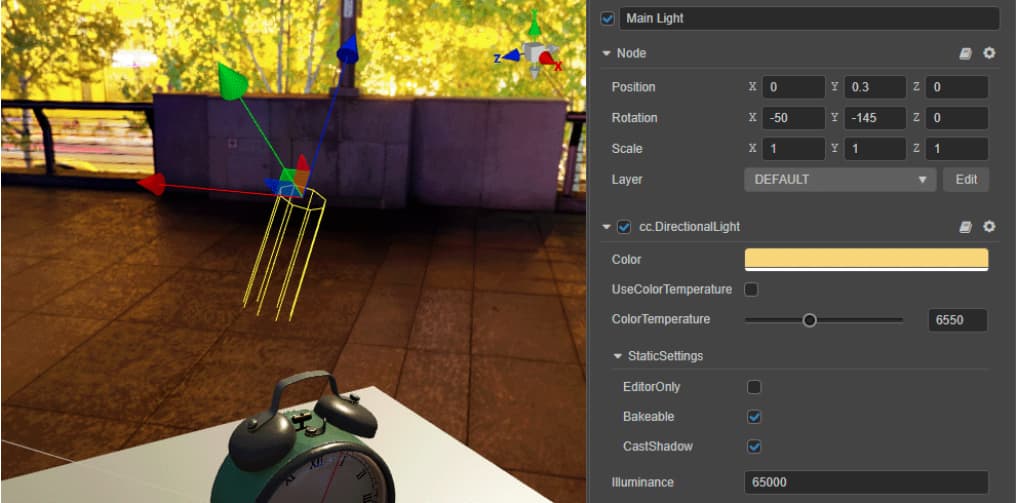
Directional light
Diffuse sky and ground reflections alone are clearly not enough to illuminate the entire scene. We also need to establish specific light sources in the scene to achieve adequate lumens.
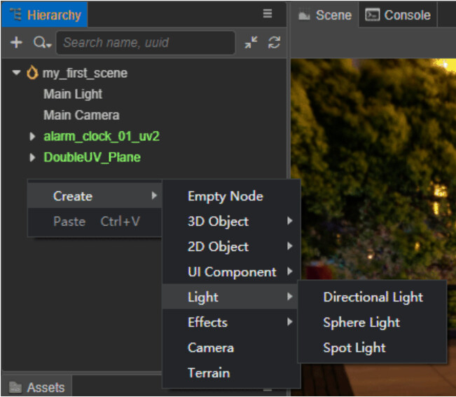
The newly created scene in Cocos Creator already contains a directional light as the main light source of the whole scene by default. We can also click the plus button in the upper left corner of the layer manager or right-click any blank part of the layer manager and select Create → Light to create a new light in the scene.
The directional light will uniformly illuminate the entire scene according to one direction, similar to the sunlight. In the process of writing the shader, we can use the built-in parameters cc_mainLitDir to obtain the relevant parameter data of the main light source.
It is true that the lighting effect in real life is not achieved by a directional light alone and depending on the scene. There may not be a need for a light source with directional light characteristics. Even so, it’s still a good idea to keep a directional light as the main light source in the scene. This is not only because the shader can easily access lighting information through a built-in parameter. The calculation of lighting usually brings a large performance burden. Using a single light source to refer to the synthesis of all lighting in the scene can reduce the number of lighting calculations. To avoid unnecessary performance issues.
Multiple directional lights can be turned on in the same scene, but only one directional light will work simultaneously.
The parameters of the directional light are very simple. Its rotation parameter represents the direction of the directional light. In addition, it also has the color parameters, intensity parameters, and color temperature parameters of the light source.
Color temperature measures the color of light in the unit of heat K (Kelvin). To put it simply: the higher the color temperature, the more bluish the light is (closer to a “cool” tone); conversely, the lower the color temperature, the more reddish the light is (closer to a “warm” tone). When the color temperature is in the range of about 6500K, the color of the light is the familiar whitish tone. Therefore, we do not need to pay too much attention to the color temperature parameter and can directly determine the color change of the light source through the color parameter.
In addition, the position parameter of the directional light will not have any effect on the lighting effect. A directional light is a light source that spreads throughout the scene. As long as the direction and intensity remain unchanged, the light source of the directional light will not cause changes in lighting effects anywhere in the scene.
Dynamic shadows
The light source is already there. The next thing we need is the shadows.
To enable dynamic shadows in the scene, you need to set the environment, model, and light source separately:
-
The first is the model. In the layer manager, select the layer where the model mesh is located, and under the LightmapSettings tab, set
ShadowCastingModetoON. -
Next is the light source, select the light source and check it under the StaticSettings tab
CastShadow. -
Finally, in the environment, select the root level of the scene in the hierarchy manager, and check
Enabledunder the Shadows tab.
There are two types of dynamic shadows in Cocos Creator, which can be selected in the Type parameter of the shadow tab. Planar is a simple shadow type that can only be cast in the direction facing the x, y, and z axes. If the object receiving the shadow is uneven or is rotated at an angle, the shadow will pass through it. The relevant settings related to these include parameters that determine the color of the shadow ShadowColor. Normal parameters determine the direction of the projection plane.
ShadowMap is a more detailed type of shadow that can be projected on any model surface. Obtaining the ideal shadow effect requires the cooperation of several parameters:
-
First, adjust
ShadowMapSizeto ensure you have enough pixels to draw the shadow. If shadows are not visible in the scene, or the shadows are rectangular, then this is the first parameter to adjust. -
Secondly, select
PcfasSOFT_2X. The Shadow Map will form jagged edges by default, and adjustingPcfsettings can enable the relevant blur algorithm to smooth the shadow edges that are too sharp.
Note:
Pcfonly performs pixel processing on the generated Shadow Map and cannot achieve the penumbra effect of the range light source.
- Adjust the value of
ShadowDistanceto reduce it if shadow detail is too low or too blurry. The effect of this adjustment is similar to that of increasing theShadowMapSizeparameter. The two can be adjusted together: if adjustingShadowDistanceto a satisfactory result can be obtained, it can be reducedShadowMapSizeto save performance.
Note: No shadows will be generated when
ShadowDistanceis equal to 0.
- Finally, adjust the
Saturationvalue, which corresponds to the translucency of the shadow.
Other light sources
In addition to directional lights, we can also add spherical and spotlights to the scene in addition to directional lights.
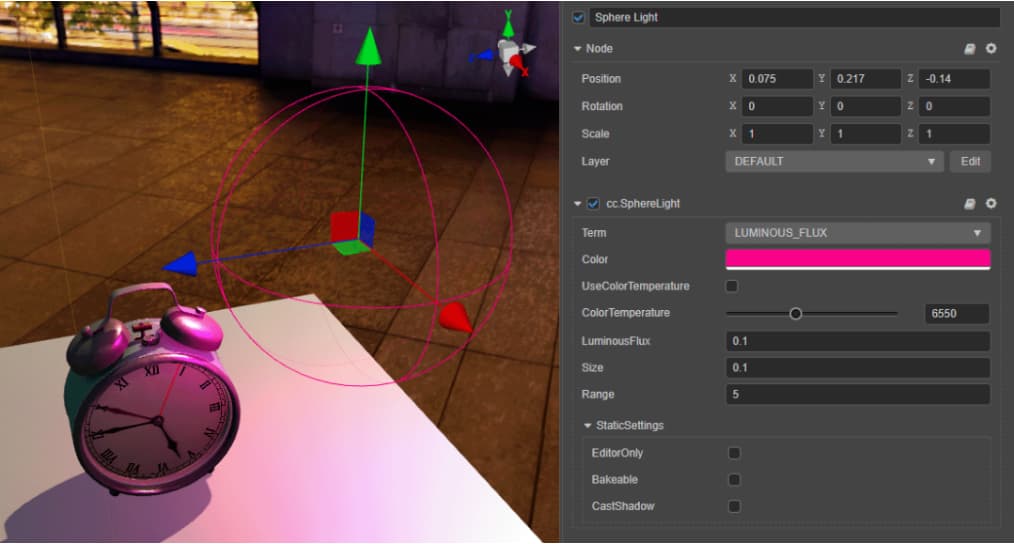
A spherical light is a light source whose light source illuminates the surroundings indiscriminately. Spherical light is a kind of light source that “lights where it is placed.” Contrary to directional light, the rotation parameters of spherical light will not affect the lighting, nor can it illuminate the entire scene indiscriminately. It can only act on a limited range. So the position parameter is the main factor in making lighting with spherical lights. Spherical lights also have parameters for color, color temperature, and intensity. In addition to this, spherical lights also have a sphere Size parameter and a Range parameter that controls the radius of the light.
Both size and range are the radius of a sphere. What’s the difference? We can think of spherical lights as a kind of shell that illuminates the surrounding environment, but the inner core is a hollow sphere, and the Size parameters determine the radius of this sphere. As the Size parameter increases, the intensity of light emitted by the entire sphere as a light source also increases. And Range determines the range that the light can reach, the increase in the range does not change the intensity of the light source.
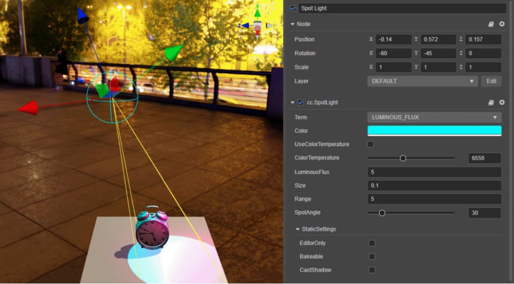
A spotlight’s light source is also a sphere, but it doesn’t emit light indiscriminately around it. Spotlights illuminate the environment in a cone-shaped area, leaving a correspondingly circular highlight area. Spotlights are the most commonly used lights on stage and in photography in real life. The position parameter of the spotlight determines the position of the light source, and the rotation parameter determines the orientation of the cone illumination range. It also has parameters of color, color temperature, intensity, light source size, and illumination range and can adjust the angle of the cone illumination range (SpotAngle).
A combination of directional, spherical, and spotlights will help us achieve detailed lighting effects. However, in the current version of Cocos Creator, both spherical lights and spotlights do not support dynamic shadows. But that doesn’t mean we can only use directional lights to achieve the effect of shadows.
Static lighting
In any game engine, dynamic lighting has a significant performance cost. A single light can double the number of Draw Calls. To complete the lighting for a scene, we usually need dozens or even hundreds of lights, and this performance loss is obviously unacceptable. Therefore, baking the light-dark relationship generated by lighting into a map has become the method chosen by mainstream game engines. In this way, the detailed light and shadow effects generated by the light can be obtained, and the complex lighting calculation can be omitted, which greatly improves the operation efficiency. However, the consequent disadvantage is that the light no longer has the function of thermal update. If the lighting effect has been baked needs to be modified, it must be re-baked.
Before baking static lighting in Cocos Creator, we need to meet a condition: all models used in the scene must have two sets of UVs, of which the second set of UVs must be limited to UDIM1001 and cannot have UV overlaps.
The reason for this restriction is also obvious: we will use mapping to store the light and dark relationships of the lights, and the use of mapping depends on the model UV placement and usage. The UV used to draw the material allows for UV overlap. After all, some parts of the model’s material can look more similar, and overlapping UVs can improve UV utilization and increase mapping accuracy. For lighting, the possibility of such overlap is almost non-existent. However, if the only purpose is to bake lighting, it requires materials to use non-overlapping and is limited to UDIM1001 UVs, which restricts the way materials are made and rendered. Therefore, the ideal approach is to have two sets of UVs, the first (UV0) mainly for materials and the second (UV1) for baking light.
This is also the solution to static lighting for mainstream engines, including Unity and Unreal Engine. Of course, Unity and Unreal Engine both provide an automatic solution for the second set of UVs. However, for projects with relatively high art requirements, art has a second set of UV solutions. Manual handling of UVs is almost a must.
In Cocos Creator, static baked lighting requires separate settings for the environment, model, light source, and material:
-
The first is the model, select the level where the model mesh is located in the level manager, under the LightmapSettings tab, have
ShadowCastingModeset toON, and checkBakeable,CastShadowandReceiveShadow.-
ShadowCastingModerole is to generate shadows. If not set, the model will not generate shadows. -
The
Bakeablefunction allows the object to join the baking queue. If it is not set, the model will continue to use dynamic lighting. -
CastShadowswitches whether the model casts shadows. -
ReceiveShadowswitches whether the model allows the projection of other models to be projected onto itself. -
lightmapSizedetermines the size of the texture baked by the model. Regarding the value of this parameter, we will expand it later.
-
-
Next is the light source. Select any light source, and check
BakeableandCastShadow. -
Then there is the environment. Select the root level of the scene in the level manager, and check
ShadowsasEnabledunder the label. -
The last is the material. Select the material used in the scene in the resource manager, and click
USE LIGHTMAPandUSE SECOND UV.
You will notice that there is some overlap between the settings for baked static lights and dynamic shadows. Of course, it is still possible to bake static lighting without shadows turned on.
After the setup is complete, select Project → Lightmap from the menu bar at the top of the editor to open the baker window.

Most of the parameters here do not need us to modify. What we need to pay attention to is:
-
MSAA: This will affect the accuracy of the baking results and, at the same time, will significantly increase the calculation time required for baking. Increasing this value can solve quality problems such as blurry and dirty baking results; -
Resolution: As the name suggests, this determines the resolution of the baked texture; -
AOColor: The default color is too light, and the baking result may not be obvious enough. When baking for the first time, you can directly choose pure black and then choose different colors according to adjustment needs.
After the setting is complete, click Lightmap Generate and select the path of the baking output in the pop-up dialog box (the default project directory/assets folder is sufficient) to start baking.
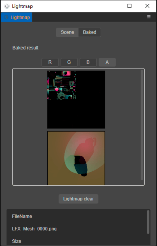
When the status bar at the bottom of the baker window prompts Build lighting 100%, the baking is completed, and we can view the preview of the baking result through the Baked tab bar. According to the previous settings, the baked texture should be stored in the project directory /assets/LightFX/output.
We can see that the bake produces two mappings, both with a resolution of 1024 × 1024 (the same setting as our Resolution in the baker ), and the mapping is shown in the preview.
Why does the baked texture look like this? We need to go back to the model to see.
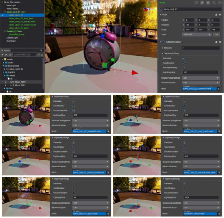
There are currently six separate models in the scene, and the main body of the alarm clock consists of 5 models: the clock body, the hour hand, the minute hand, the second hand, and the glass bezel. Except for the glass bezel, the other four models have static lighting baking turned on, and their LightmapSize is all set to 512. The ground consists of a single patch with a LightmapSize value of 1024.
Why doesn’t the glass bezel turn on for baking? Because the baker cannot distinguish the material’s opacity, the glass bezel model covers the entire clock face. If the bake is turned on, the shadow cast by the glass bezel will cover the whole clock face. Similarly, all models using translucent and fully transparent materials should not enable shadowing and baking.
Comparing our Resolution value of 1024 in the baker, we will find that the baker will bake static lighting to the map with a resolution of the baker’s resolution value, according to the size of the model’s LightmapSize value. If the model’s LightmapSize equals the baker’s Resolution, the baker will bake a separate map for this model. If the model’s LightmapSize is smaller than the baker’s Resolution, the static lighting baked by the model will only occupy a portion of the texture. The rest is reserved for static lighting maps of other models.
In this example, the model’s LightmapSize is 512, which is half the Resolution size of the baker’s, and a 1024 × 1024 texture can fit precisely 4 512 × 512 textures. Therefore, the static lighting of the clock body takes up precisely 1/4 of a baked texture. The light and shadow relationship in the map is drawn according to the second set of UVs of the model according to the lighting in the scene. As for the remaining 3/4, it corresponds to the baking results of the hour, minute, and second hands. And why they are black is only because they are small in size and in a concave position, so there is no complex light-dark relationship, and static lighting is not apparent. The ground LightmapSize has the same Resolution value as the baker, so the baker bakes a static lightmap for it.
From this, we can conclude that the LightmapSize parameter must be smaller than the Resolution parameter of the baker, and it is best to have a POW value (64, 128, 256, 512, etc.) so that the maximum baking effect can be guaranteed at the same time. The extent to utilize the space of each static lightmap.
Note: In the current version of Cocos Creator, the total number of static lightmaps in a scene cannot exceed 8.
Note: The light source’s color can be baked into a static lightmap, but the color temperature effect cannot.
How do we see the effect after baking is complete? The material’s USE LIGHTMAP and USE SECOND UV come into play here. When USE LIGHTMAP is on, the material will overlay the baked static lightmap onto the material’s output. Conversely, when USE LIGHTMAP is off, the baked static lightmaps will not be used, and the material will still use dynamic lighting.
When we no longer need static lighting, in addition to turning off USE LIGHTMAP and USE SECOND UV for the material, we can also click Lightmap clear in the baker or delete the data in /assets/LightFX in the project directory to clear the current baking information and let the scene return to use a state of dynamic lighting.
So far, we are familiar with the basic knowledge of building 3D scenes in Cocos Creator, so what skills do we have when building a scene?
Modularity of the model
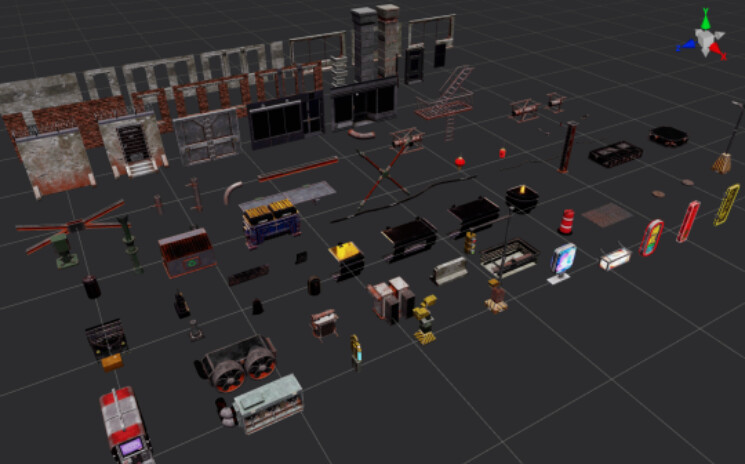
The scene 3D resources we often see in games are usually made in a modular way. So we can divide the parts that often appear in the scene into separate small pieces, import them into the engine with independent resources, and then complete the splicing of each module in the engine and give each module an independent material. Therefore, the huge building in the scene is actually composed of multiple separate wall modules. In addition to avoiding repeated work hours, this workflow can effectively prevent the problem of texture accuracy.
We know that the material performance of a 3D model depends on its UVs and the resolution of the textures used. If the UV usage is too low and/or the texture resolution is too low, we can see traces of image pixels when looking at the model up close, significantly reducing the rendering quality. However, the size of the texture is limited after all, and the game scene has a relatively high degree of compression of the texture. If it is a model with an enormous size in the scene, the situation of close-up observation will inevitably account for the vast majority. This problem is becoming more challenging to avoid. Therefore, we will cut the original large building into several modules that can be reused, and each module uses its own UV, so that the accuracy of a map can be maximized.
Conversely, for some smaller models, such as lanterns, manhole covers, trash cans, etc., we can place their UVs in the same UDIM space, allowing them to share the resources of one map.
Of course, modularity also has its drawbacks. Since the details cannot be made directly on the model, the same module is easily seen if repeated too many times, causing visual fatigue. When making modules, we can make several variants of the same type but with different details and consciously add other module embellishments to break this sense of repetition when splicing into the engine.
In addition to the first set of UVs, in order to bake static lighting, we also need to prepare a second set of UVs for the model. We have concluded that the static lighting of the model is baked according to its second set of UVs and occupies a part of a whole static lightmap, so the usage rate of the second set of UVs determines the accuracy of the static lightmap it bakes. We should maximize the utilization of the UDIM as much as possible. In other words, we want to utilize its portion of the baked static lightmap as much as possible.
In addition, when making models that need to be spliced together (such as walls, floors, etc.), it is best to set their sizes to integer values. What is the benefit of this operation? We will reveal it later.

To sum up, when we prepare the model, we should pay attention to:
-
Try to divide the model of the entire scene into smaller, reusable modules.
-
For a model with a larger size, prepare a whole map budget for it, and make full use of its first set of UVs in the UDIM space to expand it.
-
For a smaller model in the scene, let it share the same texture budget with other similarly smaller models, and let their first set of UVs share the same UDIM space.
-
Regardless of size, the second set of UVs for each module should take advantage of the UDIM space as much as possible;
-
The size of the modules to be spliced, such as walls and floors, should be an integer value.
After the model is ready, the Material ID is given accordingly, and the model file can be exported and imported into the engine.
Material assignment
After importing the model file into the resource manager, our next goal is to reassemble the different modules according to the design of the scene. Before that, we need to determine the material of each module.
We mentioned earlier that each independent module should have its own independent material. But for smaller modules, they already share a set of textures. Is it possible that they can also share material to improve running performance?
Here I have to mention two other functions of the material: Instancing and Batching.
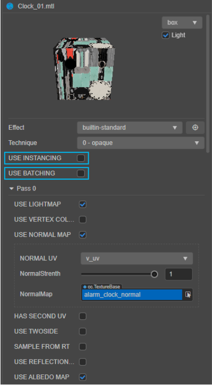
Turning on Instancing and Batching is very simple: select the material resource in the resource manager, and check USE INSTANCING or USE BATCHING in the property inspector.
Note: Instancing and batching cannot be enabled at the same time.
So, what do instancing and batching do? To put it simply: Instancing enables all nodes in the scene that use the same model and material to be merged into the same batch for rendering. Batching allows all nodes in the scene that use the same material but different models to be incorporated into the same batch for rendering.
This explanation is probably still a bit abstract. We have divided the scene into reusable modules in the model preparation stage. For example, the wall of a building can be constructed by copying several copies of the same model and using the same material. Since these wall nodes use the same model and apply the same material but are copied out of many instances, they can be classified entirely into one batch and completed at one time during rendering. Instancing plays this role: we only need to check USE INSTANCING on the material of the wall. As long as all of this wall material is the same model, no matter how many instances it is copied, it will be classified as a batch secondary rendering, thereby significantly increasing rendering efficiency.
The situation with batching is a little more complicated. In the same scene, we can usually use the continuous quad map to make materials that can be flexibly applied to different UV models. For example, we need to make a material for a glass window. Since all the glass windows in the scene are not very different, we can make only one material and then apply it to the glass window models of different shapes, structures, sizes, and UVs. So, can these nodes that share a glass material be rendered in the same batch? Although they share the same material, their models are different, so Instancing cannot be used. At this point, we can tick USE BATCHING.
In addition, we also need to arrange all the nodes that use the batching material together in the hierarchy manager. For detailed instructions on using Batching, you can refer to the official documentation:
https://docs.cocos.com/creator/manual/en/ui-system/components/engine/ui-batch.html
Baking configuration
After adjusting the material, we go back to the cc.MeshRenderer module to prepare the relevant settings for baking.
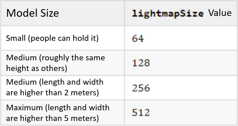
We mentioned earlier: that the total number of static lightmaps in the same scene cannot exceed 8, which does not seem like a lot. Fortunately, static lightmaps don’t require very high mapping precision. A lightmap is usually a light-dark gradient, and the accuracy of the gradient is not affected by the map’s resolution. As long as our second set of UVs is fully utilized, we don’t need to provide too high a value for lightmapSize. Depending on the scale of the model in the scene, the lightmapSize values I recommend are:
After the first bake, according to the baking result, we can click any model in the scene editor at any time (this will display its cc.MeshRenderer module directly in the property inspector) to set the parameters of the lightmapSize model individually. For example, a model that is entirely on the bright side or dark side does not need too much lighting details, so a small value can be taken. If the model casts shadows from other models, in order to increase the details of the shadow, an enormous value can be used.
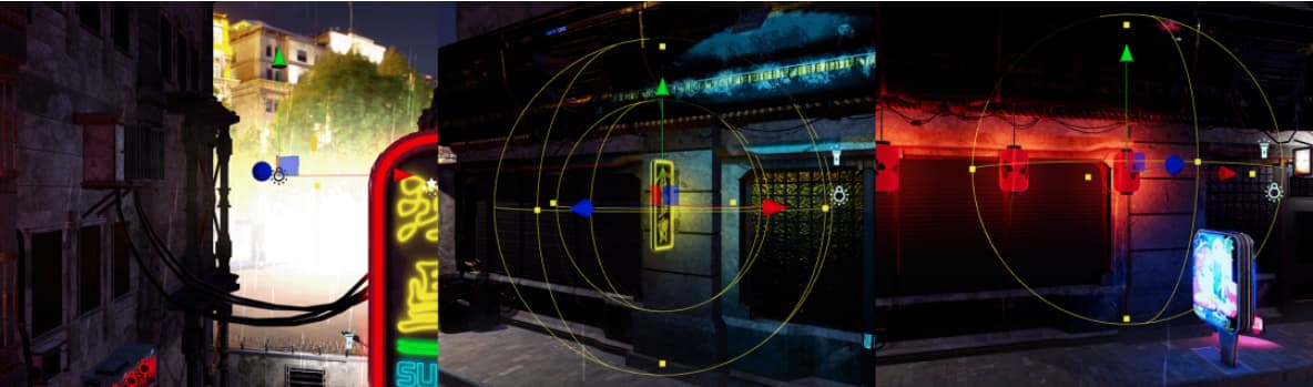
Model placement
On the surface, the model placement is an effortless task: we only need to drag the model from the resource manager to the scene editor, assign materials, adjust the position, size, rotation, and other parameters, and connect the modules that need to be spliced. Splice them together, and then copy (Ctrl/Cmd + D) out more instances and repeat the above operations.
Although simple, the model’s placement directly determines the scene’s final structure. We still need to keep control of the effect and apply specific creativity when needed:
-
Models placed, especially models that need to be spliced together, must not leave gaps between each other. It might not look obvious in the scene editor, but once static lighting is baked, these gaps often cast very thin bright edges. So, how can we effectively ensure that the models spliced together have no gaps? Remember when we made models that required the model’s size to be an integer value? As long as we place the first module in the position where the position parameter is an integer, the subsequent modules only need to enter the position of the first module + the multiple of the module size in the position parameter, and the subsequent modules can be very accurately guaranteed. Absolutely seamless. Finally, group the spliced models into a group (create a new node, drag all the models to the sub-level of the new node in the hierarchy manager). You can freely adjust the position regardless of whether the position parameter is an integer.
-
The placed models cannot use the default rotation parameters uniformly. After all, it is unlikely that you will see dozens of trash cans neatly facing you in reality.
-
Faced with dozens or even hundreds of models and an empty scene editor, you may not know where to start. At this time, we can apply the principle of “large to small” commonly used in art: begin with “first-level structure,” which mainly refers to the largest and most obvious structures, such as terrain, roads, buildings, etc.; then transition to “secondary structure.” Level structure", such as doors and windows, etc.; then to “tertiary structure,” traffic lights, trash cans, etc.; finally to “details,” such as discarded wine bottles, stacked old cartons, etc. The biggest advantage of using this method is that it can guarantee the overall degree of completion: avoid a situation where one area is full of small objects, and another area is empty.
Lighting design
We now have directional lights, sky diffuses, and ground reflections in our scene. Adjusting their color and orientation parameters according to the environment panorama map already allows the models in the scene to blend well with the background. Next, we need to use spherical lights and spotlights to make some specific designs for the scene’s lighting. In this process, what we hope to achieve is:
-
Realism, we have certain expectations about the relationship between light and shadow from the judgment of logical common sense, and we need to restore this expectation visually.
-
Richness, as the saying goes in art: “If you can use gradient, don’t use monochrome.” We hope to see more light color and intensity changes.
-
Experience, although we are pursuing the effect of art, our products still need to be oriented to the audience, so we need to control the overall experience of the scene to avoid some areas that are too bright and dazzling or can’t be seen.
The goal sounds great, so how do we achieve it with spherical lights and spotlights?
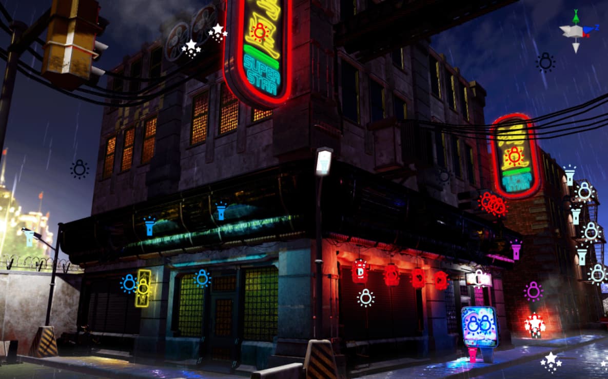
First of all, we can add corresponding light sources according to the objects expressed by the model, such as street lights, traffic lights, indoor lighting, etc. Usually, a spotlight is ideal because it has a clear circular illumination range, and it is straightforward to produce shadows. It is very easy to use it with the model to increase the realism of the light source. A monotonous white wall looks dull, but if there is a long and narrow projection projected on it, it will add a lot of interest.
Note: Cocos Creator currently does not support changing the shape of light sources using IES files.
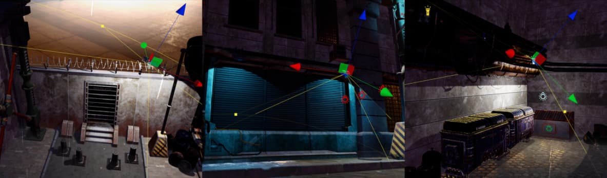
Spherical lights are an excellent tool for adding “gradients”: they are often the first choice when we don’t consider the light source but want to add lightness and color variation to an area. For example, suppose a room is too dark and needs a certain amount of brightening, without ruining its overall darkness. In that case, we can put it in a sphere and give it a cooler, darker color, avoiding darkness and adding some gradation of lightness, with the color change helping to set the mood. To create this effect, we do not need to attach a light source to all the models of the top light, but only one or several spherical lights, placed in the location of this corner to create the effect of the entire corner of the space is enveloped in light.
In addition, spherical lights can also be used with the model. For example, we need to make a lantern that radiates to the surroundings. If the light source is placed in the center of the lantern model, the model will block the light. If the light source is placed outside the model, the model will rely on the light source. The side that is too close will be overexposed. At this time, we only need to adjust the Size parameters of the spherical light so that it wraps the entire lantern model. We can use the spherical light to illuminate the surroundings of the lantern without the lantern model itself being affected by the spherical light.
Other
Now that the models and lighting are in place, are there any other ways we can enhance the scene? In Cocos Creator, we can also use other means to add color to the scene.
Fog effect
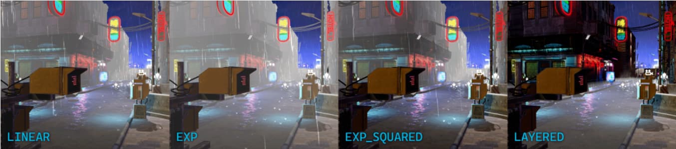
Turning on the fog effect is very simple. Select the root level in the level manager and open it under the Fog tab Enabled. Fog effects in Cocos Creator include regular fog and layered fog, which can be switched in the Type parameters. When enabled Accurate, you can upgrade from voxel-level fog rendering to pixel-level to obtain more delicate effects at the expense of certain performance.
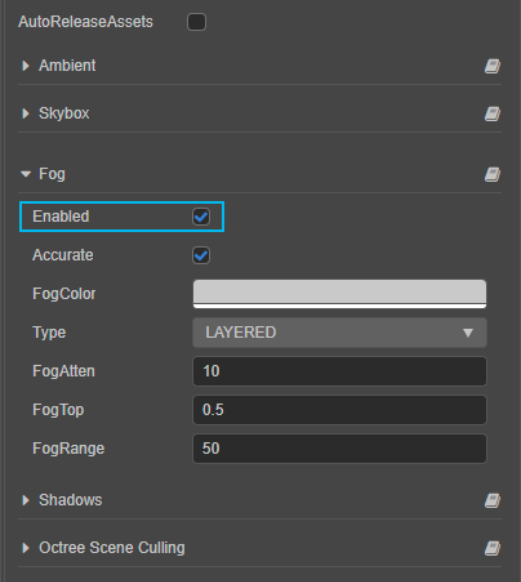
Regular fog is a fog effect we’re accustomed to: the close-up view is visible, and a layer of translucent gradient gradually covers the distant view. Cocos Creator provides three types of regular fog: LINEAR, EXP, EXP_SQUARED. The difference between the three is the gradient curve (straight line and exponential curve), in which EXP_SQUARED is the gradient curve closest to reality. Layered fog starts from the ground level and covers a certain fog height.
Billboard
Billboard is a 2D image rendering method, and the rendered 2D image is always facing the camera direction. In the age of immature 3D technology, Billboard is usually used to render 2D Sprite into a 3D environment (commonly known as 2.5D). Using Billboard’s ability to always face the camera, we can use a gradient map to create the illusion of a volumetric light quickly.
Using Billboard is very simple. Click the plus button in the upper left corner of the hierarchy manager, or right-click in an empty area and select Create → Empty Node. Then, click on the newly created empty node, click Add Component at the end of the property inspector, and select Effect → Billboard. In the cc.Billboard module, assign a map, use the Height and Width parameters to adjust the following size, and move the node to the appropriate position in the scene.
Particles
Whether it’s fog or billboard, they can only do changes in color and brightness to set the mood and create the illusion of environmental characteristics. When we need more complex and specific environmental effects, we need to use the particle system. This will be explained in a future article.