
What Can A Vertex Shader Do? Cocos Creator Creates A Simulation Of A Cloud Sea
Since Cocos Creator 3.3.1, we were able to build this amazing demo that simulates the effect of the sea of clouds. In this tutorial, we will write the vertex shader step by step to modify the shape of the model. Let’s learn about the Mesh model, vertex shader, fragment shader, and noise effect.
This article focuses on sharing the “things that vertex shaders can do”, and does not really want to simulate a real sea of clouds. After all, there is still a certain gap compared to the >effects of RAYMarching volume clouds.
Here is how we’ll be creating this effect:
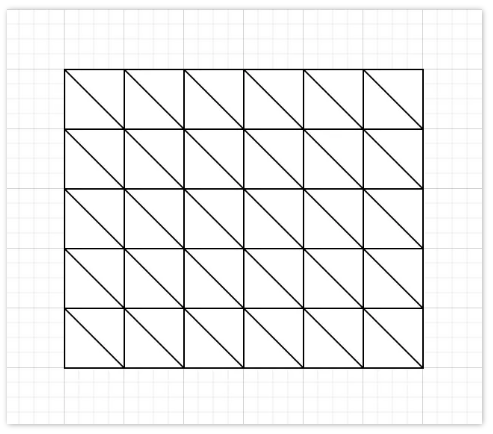
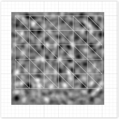
The shape of the Mesh used here is a rectangle. The graphics card can only draw triangles, so to draw a rectangle, at least two triangles must be spliced together. If there are many small rectangles to form a large rectangle, it is actually equivalent to having many small triangles to form a large rectangle.
The vertex shader only modifies the Y-axis of the model and does not change it much. The change of the vertex shader is only obtained from the noise map, no complex formula is used to calculate it, so it is also easy to understand.
The slice shader is simpler, it just returns the v_color of the vertex shader output, and the value output by the vertex shader will be delta based on the barycentric coordinates.
Noise is a picture that is only black and white, so it is easy to understand.
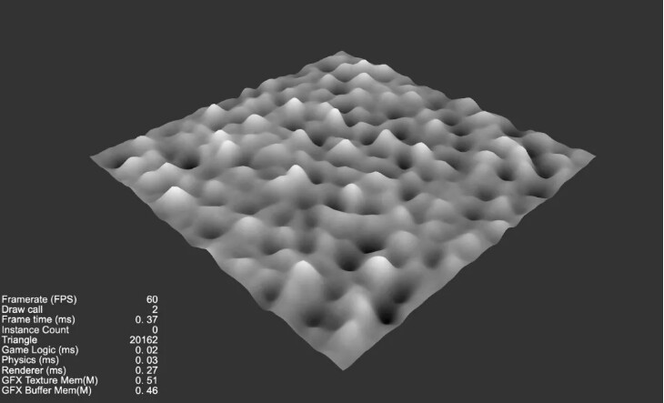
Effect preview
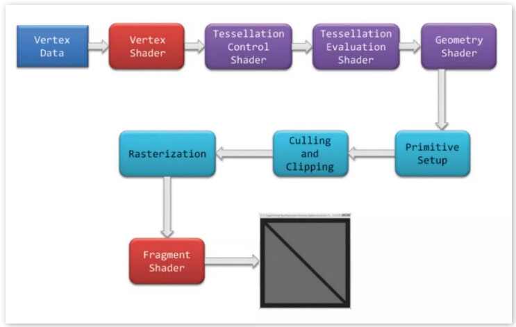
Combining our known knowledge, we can sort out that:
- The GPU renders the triangles one by one.
- A 3D image with enough vertices produces a smooth surface - so, on low-end machines, you need to have fewer triangles [vertices].
- Dynamically generate a Mesh, which is a plane and has enough triangles.
- The information about the concave and convexity of the cloud is stored through the information of an external picture [noise] - one can think of a picture with only black, white and gray, the whiter it is, the higher the height of the triangle is made, and vice versa.
- Let the texture move [roll], and as time changes, modify the position information of the UV acquisition - so that the triangle can change.
- By reading multiple noises, or reading different positions of the same noise, and superimposing them, you can get the feeling of tumbling.
Next, get to the point, get started!
Due to space limitations, this article only shows part of the core code. For the complete code and Demo project, please go to the forum discussion thread to view and download:
Cocos3.x Shader 学习Shader顶点着色器 简单模拟云海的效果 - Creator 3.x - Cocos中文社区
1. Prepare
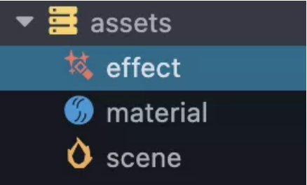
First create the default scene, material, and effect files.
2. Edit the effect file
Double-click to open the effect, add the default Cocos Shader file, and find this line:
- vert: general-vs:vert # builtin header
According to the following comments, the default built-in vertex shader is used here, please refer to the official Cocos documentation for Effect Syntax.
The vertex shader to be written is missing from this file, one needs to be added manually.
Find general-vs in the built-in chunks and copy the content.
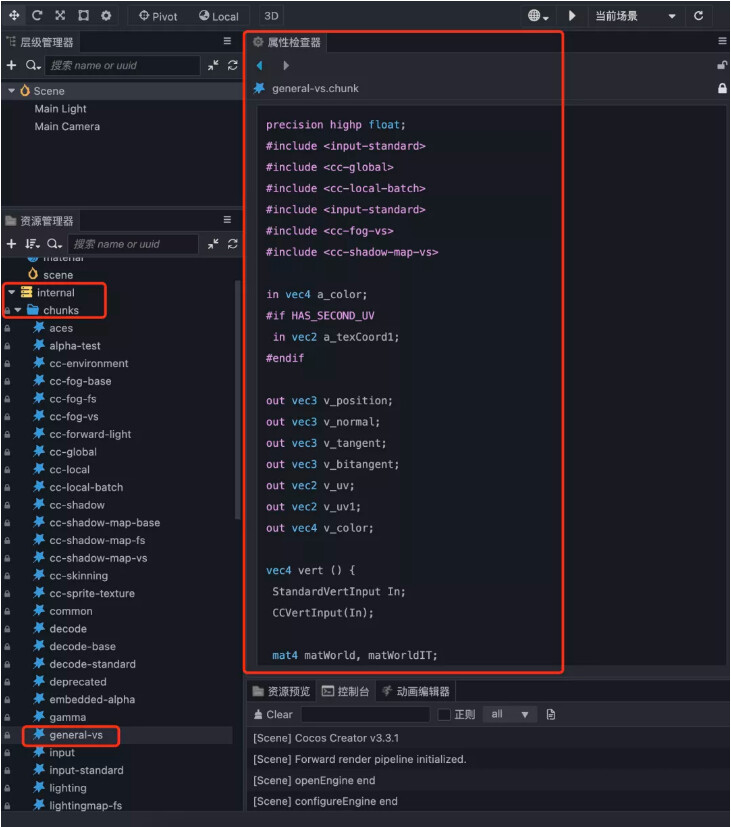
Back in the effect file, add a CCProgram block my-vs:
CCProgram my-vs %{

  precision highp float;
  #include <input-standard>
  #include <cc-global>
  #include <cc-local-batch>
  #include <input-standard>
  #include <cc-fog-vs>
  # include <cc-shadow-map-vs>

  in  vec4 a_color;
  # if  HAS_SECOND_UV
    in  vec2 a_texCoord1;
  #endif

  out vec3 v_position;
  out vec3 v_normal;
  out vec3 v_tangent;
  out vec3 v_bitangent;
  out vec2 v_uv;
  out vec2 v_uv1;
  out vec4 v_color ;

  vec4 vert () {
    StandardVertInput In;
    CCVertInput(In);

    mat4 matWorld, matWorldIT;
    CCGetWorldMatrixFull(matWorld, matWorldIT);

    vec4 pos = matWorld * In.position;

    v_position = pos.xyz;
    v_normal = normalize((matWorldIT * vec4(In.normal,  0.0 )).xyz);
    v_tangent = normalize((matWorld * vec4 (In.tangent.xyz,  0.0 )).xyz);
    v_bitangent = cross(v_normal, v_tangent) * In.tangent.w;  // note the cross order

     v_uv = a_texCoord;
    # if  HAS_SECOND_UV
      v_uv1 = a_texCoord1;
    #endif
    v_color = a_color;

    CC_TRANSFER_FOG(pos);
    CC_TRANSFER_SHADOW(pos);

    return  cc_matProj * (cc_matView * matWorld) * In.position;
  }

}%
And modify the definition of the vert part of the top CCEffect to: my-vs:vert
CCEffect %{
  techniques:
  - name: opaque
    passes:
    - vert: my-vs:vert # builtin header
      frag: unlit-fs:frag
      properties: &props
        mainTexture: { value: white }
        mainColor: { value: [ 1 ,  1 ,  1 ,  1 ], editor: {  type : color } }
  - name: transparent
    passes:
    - vert: general-vs:vert # builtin header
      frag: unlit-fs:frag
      blendState:
        targets:
        - blend:  true
           blendSrc: src_alpha
          blendDst: one_minus_src_alpha
          blendSrcAlpha: src_alpha
          blendDstAlpha: one_minus_src_alpha
      properties: *props
}%
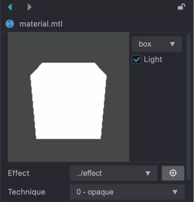
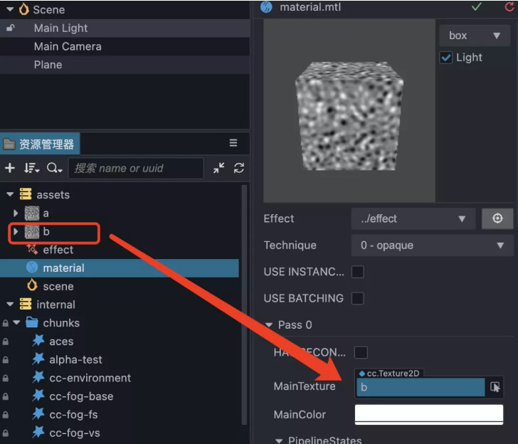
3. Bind the effect to the material
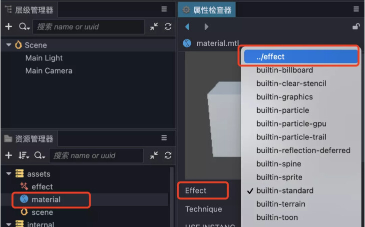
Select the material, select Effect, select the newly created effect file, and finally don’t forget to click the arrow in the upper right corner to save it. If it is correct, a solid white square will be previewed.
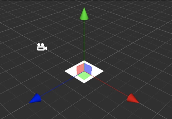
4. Create a Plane and apply a material
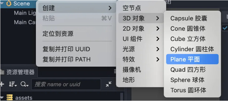
Create a 3D object in the scene, Plane.
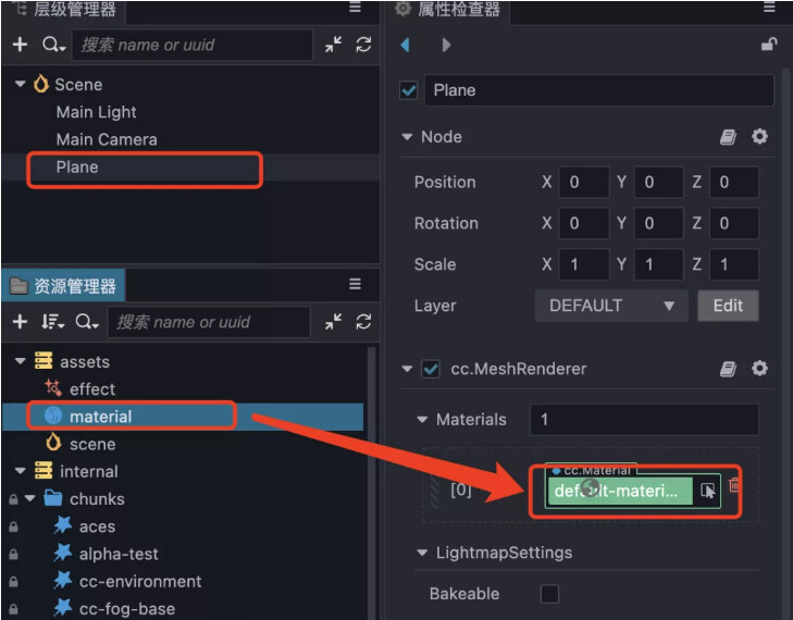
Select the Plane node, drag the material to cover the original default-material material, and finally get a pure white Plane.
5. Prepare the noise map
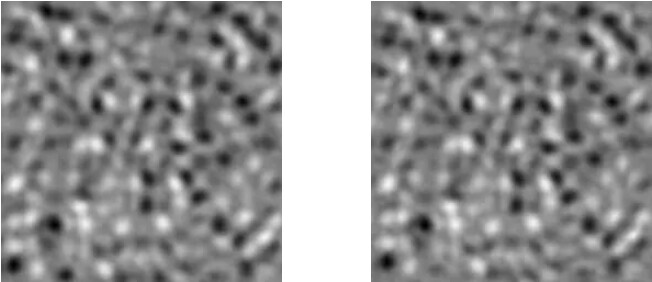
There are two noises here, they don’t seem to be different, but if you offset the UVs by 0.5, a strange problem occurs. Now let’s test it.
First simply modify the next fragment shader, which is the frag block:
CCProgram unlit-fs %{
  precision highp float;
  #include <output>
  #include <cc-fog-fs>

  in  vec2 v_uv;
  uniform sampler2D mainTexture;

  uniform Constant {
    vec4 mainColor;
  };

  vec4 frag () {
    vec4 col = mainColor * texture(mainTexture, v_uv +  0.5 );
    CC_APPLY_FOG(col);
    return  CCFragOutput(col);
  }
}%
Note: The value of UV is modified here, and v_uv is increased by 0.5.
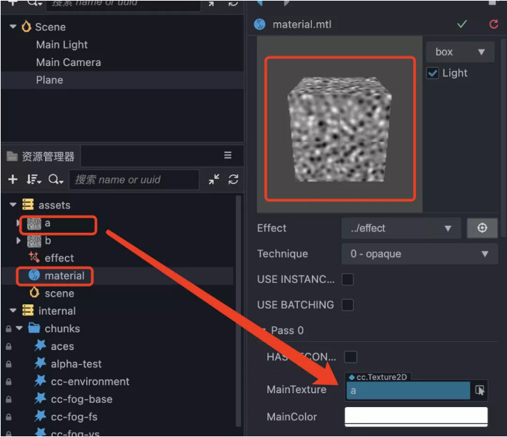
Go back to Cocos Creator, put two noises into the material separately, and see what happens.
It can be clearly found that the noise is not smooth in the middle after the offset. So the noise map used here has one condition: seamless noise.
Remember to delete +0.5 after the test!
6. Modify the vertex shader
Define mainTexture.
Define p = In.position, and replace In.position with p in subsequent code.
The noise map is mapped on the rectangle, and the corresponding vertices of each triangle on the rectangle are judged whether the color is blacker or whiter, and the y value of this vertex is determined according to the depth of the color value. In the shader, the color range is 0~1, so now the y of each vertex has height information, that is, the value range is 0~1.
And, because it is black, white and gray noise, so r=g=b, directly assign the color of r to py.
uniform sampler2D mainTexture;

  vec4 vert () {
    StandardVertInput In;
    CCVertInput(In);

    mat4 matWorld, matWorldIT;
    CCGetWorldMatrixFull(matWorld, matWorldIT);

    vec4 p = In.position;

    float y = texture(mainTexture, a_texCoord).x;
    py = y;


    vec4 pos = matWorld * p;

    v_position = pos.xyz;
    v_normal = normalize((matWorldIT * vec4(In.normal,  0.0 )).xyz);
    v_tangent = normalize((matWorld * vec4(In.tangent.xyz,  0.0 )).xyz);
    v_bitangent = cross(v_normal, v_tangent) * In.tangent.w;  // note the cross order

     v_uv = a_texCoord;
    # if HAS_SECOND_UV
      v_uv1 = a_texCoord1;
    #endif
    v_color = a_color;

    CC_TRANSFER_FOG(pos);
    CC_TRANSFER_SHADOW(pos);

    return  cc_matProj * (cc_matView * matWorld) * p;
  }
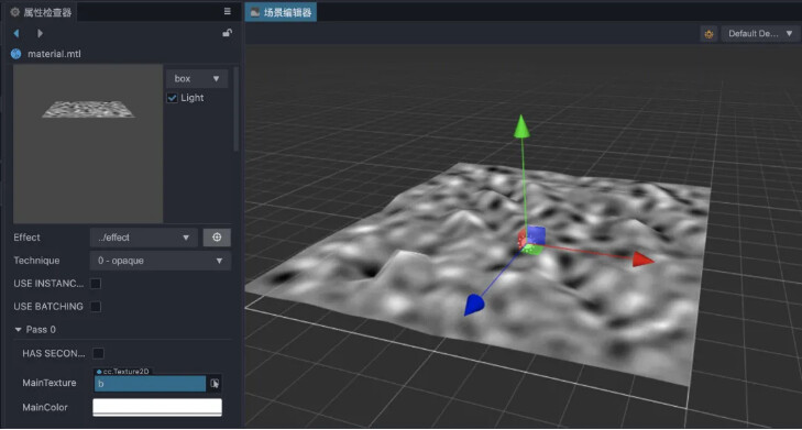
Going back to Cocos Creator, you can find that the Plane has become uneven, and the darker the lower, the whiter the higher.
7. Smooth
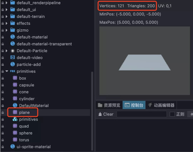
The default Plane has fewer faces, so it becomes less smooth.
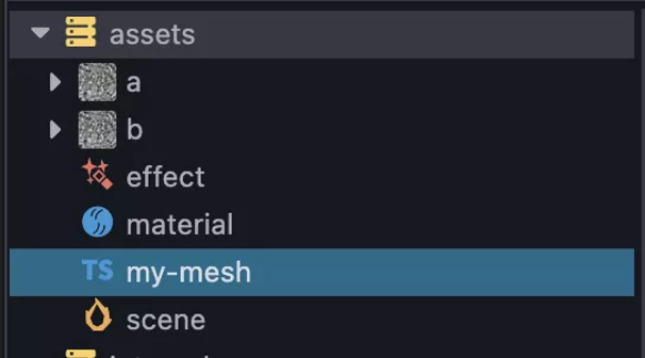
Create a script, called my-mesh, to replace the default mesh for plane:
import  { _decorator, Component, utils, primitives, MeshRenderer }  from  'cc' ;

const  { ccclass, property } = _decorator;


@ccclass ( 'MyMesh' )
export  class  MyMesh  extends  Component {
    start () {
        const  renderer =  this .node. getComponent(MeshRenderer);
        if (!renderer){
            return ;
        }
        const  plane: primitives.IGeometry = primitives.plane({
            width:  10 ,
            length:  10
             widthSegments:  100,
            lengthSegments:  100 ,
        });

        renderer.mesh = utils.createMesh(plane);
    }

}
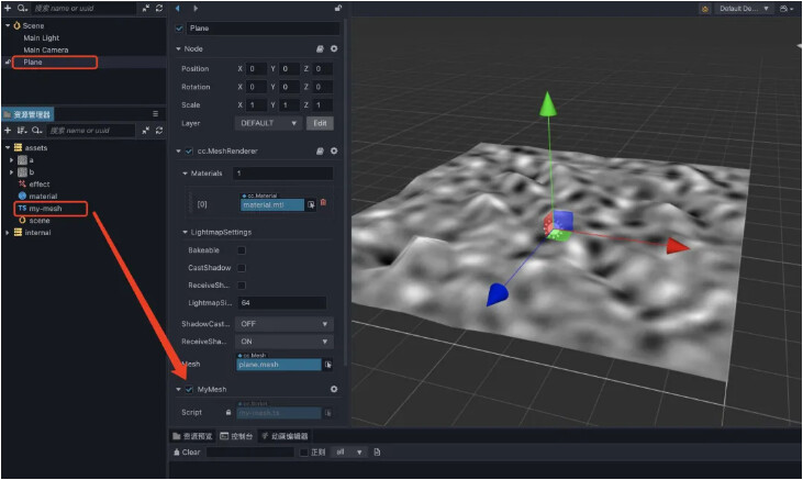
Go back to Cocos Creator, bind the script to the Node, and run it. It can be seen that it has been smoothed a lot in the relative editor, and it is easy to distinguish between high and low colors.
8. Exercise
The time stamp (unit: s) is introduced, and according to the time difference, the UV information of different positions can be obtained, and the screen can be scrolled.
Introducing #incloud cc-global.
Modify the acquisition of UV, a_texCoord value plus cc_time.x and * a speed factor 0.1.
uniform sampler2D mainTexture;

  #include <cc-global>
  vec4 vert () {
    StandardVertInput In;
    CCVertInput(In);

    mat4 matWorld, matWorldIT;
    CCGetWorldMatrixFull(matWorld, matWorldIT);

    vec4 p = In.position;

    float y = texture(mainTexture, a_texCoord + cc_time.x *  0.1 ).x;
    py = y;


    vec4 pos = matWorld * p;

    v_position = pos.xyz;
    v_normal = normalize((matWorldIT * vec4(In.normal,  0.0 )).xyz);
    v_tangent = normalize((matWorld * vec4(In.tangent.xyz,  0.0 )).xyz);
    v_bitangent = cross(v_normal, v_tangent) * In.tangent.w;  // note the cross order

    v_uv = a_texCoord;
    # if  HAS_SECOND_UV
      v_uv1 = a_texCoord1;
    #endif
    v_color = a_color;

    CC_TRANSFER_FOG(pos);
    CC_TRANSFER_SHADOW(pos);

    return  cc_matProj * (cc_matView * matWorld) * p;
  }

}%
9. Color
The shape has changed, but the color doesn’t seem to change again.
Modify the vertex shader and directly throw the color obtained by the texture function to v_color.
Modify the fragment shader to return the v_color color directly (remember to declare in vec4 v_color first).
CCProgram my-vs %{

  precision highp float;
  #include <input-standard>
  #include <cc-global>
  #include <cc-local-batch>
  #include <input-standard>
  #include <cc-fog-vs>
  # include <cc-shadow-map-vs>

  in  vec4 a_color;
  # if  HAS_SECOND_UV
    in  vec2 a_texCoord1;
  #endif

  out vec3 v_position;
  out vec3 v_normal;
  out vec3 v_tangent;
  out vec3 v_bitangent;
  out vec2 v_uv;
  out vec2 v_uv1;
  out vec4 v_color ;

  uniform sampler2D mainTexture;

  #include <cc-global>
  vec4 vert () {
    StandardVertInput In;
    CCVertInput(In);

    mat4 matWorld, matWorldIT;
    CCGetWorldMatrixFull(matWorld, matWorldIT);

    vec4 p = In.position;

    vec4 baseColor0 = texture(mainTexture, a_texCoord + cc_time.x *  0.1 );
    py = baseColor0.x;


    vec4 pos = matWorld * p;

    v_position = pos.xyz;
    v_normal = normalize((matWorldIT * vec4(In.normal,  0.0 )).xyz);
    v_tangent = normalize((matWorld * vec4(In.tangent.xyz,  0.0 )).xyz) ;
    v_bitangent = cross(v_normal, v_tangent) * In.tangent.w;  // note the cross order

     v_uv = a_texCoord;
    # if  HAS_SECOND_UV
      v_uv1 = a_texCoord1;
    #endif
    v_color = baseColor0;

    CC_TRANSFER_FOG(pos);
    CC_TRANSFER_SHADOW(pos);

    return  cc_matProj * (cc_matView * matWorld) * p;
  }

}%

CCProgram unlit-fs %{
  precision highp float;
  #include <output>
  #include <cc- fog-fs>

  in  vec2 v_uv;
  in  vec4 v_color;
  uniform sampler2D mainTexture;

  uniform Constant {
    vec4 mainColor;
  };

  vec4 frag () {
    return  v_color;
  }
}%
It can be found that there is no problem just now, the higher the whiter the place, the darker the place.
10. Noise superposition - surge
The noise can be used multiple times or read multiple times. As long as the reading positions are different and superimposed, you can get the feeling of surging.
Tiling0 and tiling1 are defined, where xy is used to control the magnification of UV, and zw is used to control the direction of UV movement.
The texture is sampled twice, baseColor0 and baseColor1, respectively, and the red of the two colors is added up to *0.5, and assigned to py.
py is still -0.5 at the end, because the value of y was originally between 0 and 1, and it is hoped that it will be distributed between -0.5 and 0.5 in the end, so the overall value is -0.5.
Change v_color = baseColor0 to v_color = (baseColor0 + baseColor1)* 0.5.
vec4 vert () {
    StandardVertInput In;
    CCVertInput(In);

    mat4 matWorld, matWorldIT;
    CCGetWorldMatrixFull(matWorld, matWorldIT);

    vec4 p = In.position;

    vec4 tiling0 = vec4( 1.0 ,  1.0 ,  0.1 ,  0.1 );
    vec4 tiling1 = vec4 ( 1.0 ,  1.0 ,  0.07 ,  0.07 );
    vec4 baseColor0 = texture(mainTexture, a_texCoord * tiling0.xy + cc_time.x * tiling0.zw);
    vec4 baseColor1 = texture(mainTexture, a_texCoord * tiling1.xy + cc_time.x * tiling1 .zw);
    py = (baseColor0.x + baseColor1.x) *  0.5 -  0.5 ;


    vec4 pos = matWorld * p;

    v_position = pos.xyz;
    v_normal = normalize((matWorldIT * vec4(In.normal,  0.0 )).xyz);
    v_tangent = normalize((matWorld * vec4(In.tangent.xyz) ,  0.0 )).xyz);
    v_bitangent = cross(v_normal, v_tangent) * In.tangent.w;  // note the cross order

     v_uv = a_texCoord;
    # if  HAS_SECOND_UV
      v_uv1 = a_texCoord1;
    #endif
    v_color = (baseColor0 + baseColor1)*  0.5 ;

    CC_TRANSFER_FOG(pos);
    CC_TRANSFER_SHADOW(pos);

    return  cc_matProj * (cc_matView * matWorld) * p;
  }
It can be found that the movement is no longer a single movement like the above, but brings a feeling of ups and downs.
11. Color transition
Black, white and gray are not good-looking after all, so we customize two colors (c0 and c1) to redefine the high and low.
vec4 c0 = vec4(1.0, 0.0, 0.0, 1.0);
vec4 c1 = vec4(0.0, 1.0, 0.0, 1.0);

v_color = (py + 0.5) * (c0 - c1) + c1;
c0 represents the color at the highest point.
c1 represents the color at the lowest point.
c0 - c1 = the difference between the two colors.
py + 0.5 gets a value between 0 and 1, which is used to represent the current y height.
(py + 0.5) * (c0 - c1) get a transition value in y height change.
Transition value + c1, indicating transition value + base value = final color.
c0 - c1 is equal to the difference of the two color components, use the difference * (y + 0.5) to get the change value, and finally add c1.
In this way, a Shader with a custom color is obtained.
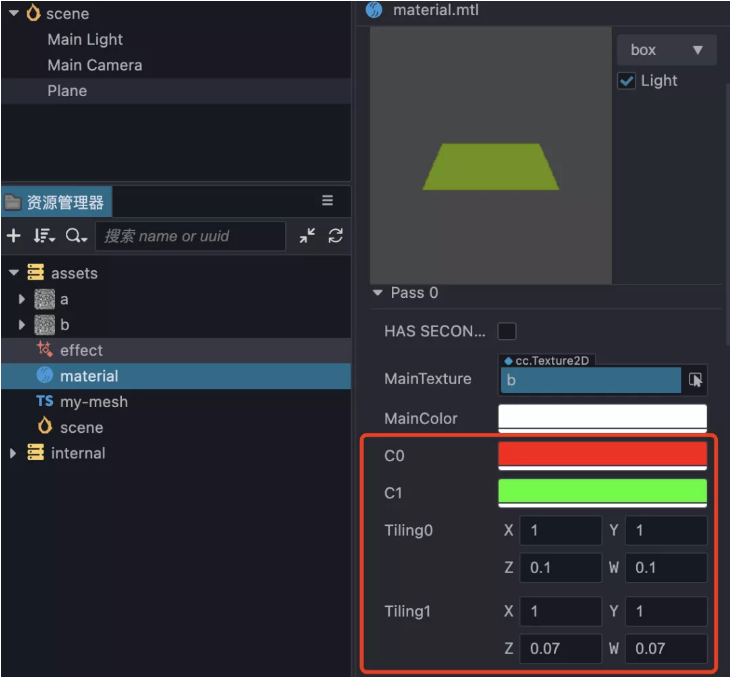
12. Expose the defined data to the material panel
At the current position, two tilings are defined here, two colors c0 and c1:
CCEffect %{
  techniques:
  - name: opaque
    passes:
    - vert: my-vs:vert # builtin header
      frag: unlit-fs:frag
      properties: &props
        mainTexture: { value: white }
        mainColor: { value: [ 1 ,  1 ,  1 ,  1 ], editor: {  type : color } }
        c0: { value: [ 1 ,  0 ,  0 ,  1 ], editor: {  type : color } }
        c1: { value: [ 0 ,  1 ,  0 ,  1], editor: {  type : color } }
        tiling0: { value: [ 1.0 ,  1.0 ,  0.1 ,  0.1 ] }
        tiling1: { value: [ 1.0 ,  1.0 ,  0.07 ,  0.07 ] }
  - name: transparent
    passes:
    - vert: general -vs:vert # builtin header
      frag: unlit-fs:frag
      blendState:
        targets:
        - blend:  true
           blendSrc: src_alpha
          blendDst: one_minus_src_alpha
          blendSrcAlpha: src_alpha
          blendDstAlpha: one_minus_src_alpha
      properties: *props
}%
Define c0, c1, tiling0, and tiling1 into properties. The original parameters will not be deleted and processed here.
Add the uniform declaration definition block to both the vertex shader and the fragment shader:
uniform MyVec4 {
    vec4 c0;
    vec4 c1;
    vec4 tiling0;
    vec4 tiling1;
  };
Then remove the c0, c1, tiling0 and tiling1 defined in the original code and replace them with uniform.
After finishing, go back to Cocos Creator and check the material.
13. Finished product and Demo
Finally, adjust the parameters of the camera and material to get the finished product:
The completed effect file content can be found here:
Demo project & Chinese forum discussion thread: Cocos3.x Shader 学习Shader顶点着色器 简单模拟云海的效果 - Creator 3.x - Cocos中文社区