Understanding the principles of the Cocos Creator 3.0 coordinate conversion
How does Cocos Creator 3.0 convert world coordinates to screen coordinates? How does Creator 3D coordinates to the Canvas? How to convert the touch screen coordinates to world coordinates? How to convert node coordinates under Canvas to 3D scene coordinates?
On the Cocos Chinese community, you can see discussion posts related to coordinate conversion from time to time. Today
Outline overview
PART 1. - Screen coordinates
PART 2. - UI contact coordinates
PART 3. - Conversion between different coordinates
PART 4. - Radiographic Inspection

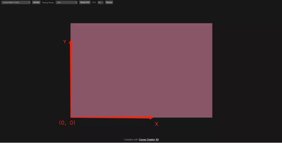
Screen coordinates
The canvas size displayed in Cocos Creator 3.0 is the screen area. The screen coordinates are calculated from the lower left corner of the canvas as the origin. The screen size can be obtained through the view.getCanvasSize API interface.
To know the starting point of the screen and the size of the screen, you can roughly estimate the position of the touch point when you click on the screen. Touch events can just help to verify, through systemEvent to monitor:
1    // Monitor system touch movement events
2    onEnable () {
3        systemEvent.on(SystemEventType.TOUCH_MOVE, this._touchMove, this);
4    }
5
6    _touchMove(touch: Touch, event: EventTouch){
7        // Print the acquired position of the screen touch point
8        console.log(touch.getLocation());
9    }
After clicking and moving, you can see the direction of the coordinate value. The more right you click, the greater the x value, and the higher it is, the greater the y value.
In Cocos Creator 3.0, the size of the 3D camera is always the same as the screen size without setting the viewport. This is very important, because the following content cannot be separated from the camera.

UI touch point coordinates
The biggest feature of the UI is adaptation and interaction. When looking at the UI documentation, you may get several sections that are most directly related to the adaptation, such as the design resolution, layout component (Layout), alignment component (Widget), multi-resolution adaptation schemes, etc. Among them, the design resolution and multi-resolution adaptation scheme are directly related to the coordinates. This is mentioned in the official document multi-resolution adaptation scheme. I will quickly help you to understand the adaptation based on this knowledge here and how the rules affect the presentation of UI content.
UI multi-resolution adaptation scheme
In UI production, the size of the UI design is usually determined first, which is called the design resolution. The design resolution and adaptation mode determine the UI content size at runtime (the size of the UI root node Canvas). The condition that must be clearly known here is that the design resolution and device resolution (screen resolution) must be fixed. Under this condition, understand the two modes suitable for most game development, namely the fit width and fit height.
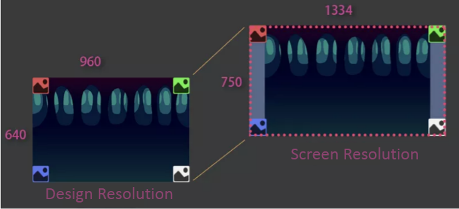
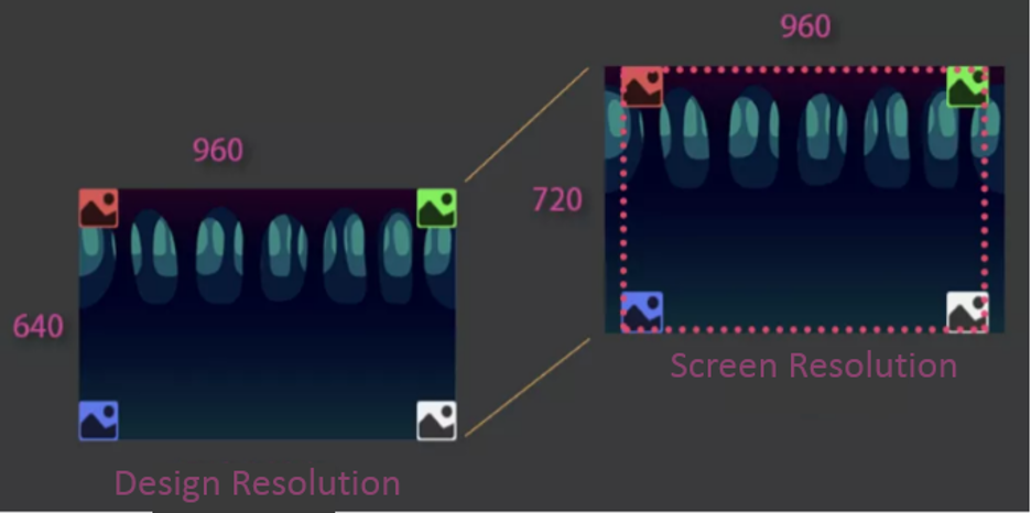
Here is an example to illustrate. Assuming that the design resolution is 960x640, the UI has a background of the same size as the design resolution (no widget added) plus four sprites that are always close to the four corners of the UI content area (all four sprites have a widget component, which are top, bottom, left, and right, close to the four corners of the UI content area).
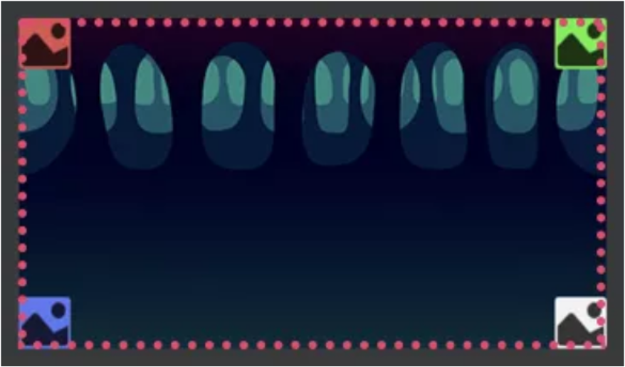
When you have selected the screen-adaptation scheme and the screen resolution is 1334x750, the engine will automatically fill the height of the screen with the height of the design resolution, that is, enlarge the scene image to 750 / 640 = 1.1718 times, but this zoom in won’t fill all of the width (960 * 1.1718 = 1125) making black borders are prone to appear (the game in the figure below does not cover the entire screen). This method is definitely a situation that most game developers don’t want to see. Therefore, the engine will automatically “cover” the screen width based on the widget component calculation (four sprites in the following figure).
Of course, this method also has drawbacks, that is, if the background is fully adapted to the design resolution size (adapting component Widget is added, and the UI content area is adapted up and down at the same time), it will be stretched to a certain extent. Here, because the stretching ratio is small, it is not very obvious, and interested friends can verify by themselves.
Conversely, if the screen resolution used is 960 x 720, the scene image is enlarged to 720 / 640 = 1.125, the enlarged width is 1.125 * 960 = 1080, which is greater than the screen width 960, so that content clipping will occur (as shown in the figure below). Therefore, the engine will automatically “limit” the width within the screen based on the widget component calculation (the four sprites in the figure below). The disadvantage of this method is that the background will be squeezed if it fully adapts to the design resolution.
The same principle applies to the adaptation width. Understand the principle of adaptation, you can choose a suitable adaptation scheme according to different platforms.
UI touch point acquisition
In the UI, what everyone should be most concerned about is how to set UI elements according to the position of the touch point.
For the Creator 2.x users, you can get contact information in the event listener callback method through event.getLocation, where the contact information is calculated based on the contact screen UI content area.
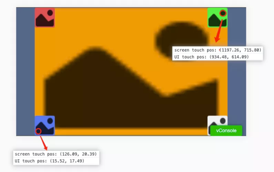
For the Creator 3.0 users, the screen and UI are completely separated, and users can tap the screen to get contact information without UI. Therefore, to get the screen touch point is through event.getLocation(). If you want to obtain the coordinates of the “screen touch point” in the same way as Creator 2.x, you can get it by event.getUILocation(). The contact information obtained by event.getUILocation() can also be used to directly set the world coordinates of UI elements (because every pixel on the UI is equivalent to every unit in 3D, so you can directly set the UI element’s coordinates according to this coordinate point.)
const location = touch.getLocation();
console.log(`screen touch pos: ${location}`);
const locationUI = touch.getUILocation();
console.log(`UI touch pos: ${locationUI}`);
const pos = new Vec3(locationUI.x, locationUI.y, 0);
// The sprite here is a reference to the white picture on the screen
this.sprite.setWorldPosition(pos);
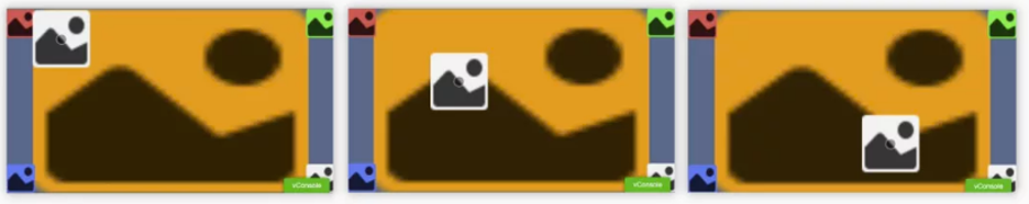
Of course, it is possible to directly use the screen coordinates and UI camera to process. For the specific principle, please refer to the screen coordinates and 3D node world coordinates conversion below.
// This script is mounted on the Canvas node

// Get screen coordinates
const location = touch.getLocation();
const screenPos = new Vec3(location.x, location.y, 0);
const pos = new Vec3();
const canvas = this.getComponent(Canvas)!;
// Get the camera data of the camera associated with Canvas
const uiCamera= canvas.cameraComponent?.camera!;
// Use camera data objects to convert screen points to values in world coordinates
uiCamera.screenToWorld(pos, screenPos);
this.sprite.setWorldPosition(pos);
Note: this is because the UI does not have depth information, so you can directly set the world coordinates and fix the z value to 0. If it is a 3D node, also consider the depth.
Note: it is expected that the version 3.4 and later will be unified with the camera to convert, you don’t need to understand the concept of UI touch points, and the corresponding conversion method will be provided later.

Conversion between different coordinates
After understanding the screen coordinates, UI coordinates, and the camera, you can do more conversions between coordinates. First we’ll explain the relationship between local coordinates and world coordinates:
The center point of the world coordinates (also called the origin) is created by the node in the scene. It is located at the outermost layer of the node tree and its positon attribute value is all 0. This is the center point of the world coordinates. The value obtained by all nodes through the node.getWorldPosition interface is the offset value of the position, which can also be understood as the absolute difference value. Local coordinates are the offset relative to the parent node. Assuming that the world coordinates of node A are (0, 10, 0), node B is the direct child of node A, and the local coordinates of node B are (0, 10, 0), and both nodes A and B are not rotated or scaled, then what is the world coordinate of node B?
The obvious answer is (0, 20, 0). The coordinates of node B are local coordinates, and the local coordinates are the offset relative to the parent node. When the value is shifted by 10, then it can be calculated that B is shifted by 10 + 10 = 20 from the world origin y value.
Conversion between screen coordinates and 3D node world coordinates
Before performing the work of converting 3D node positions to screen coordinates, we must first understand how 3D objects are finally rendered on the screen.
First of all, all objects need to be illuminated by the camera before they can be displayed. Therefore, the objects need to be within the camera’s line-of-sight frame, where an operation from world space to camera space is required. Secondly, depth detection and other operations need to be done in the camera space, and finally, the space content is projected to the screen. To understand this part, look at the picture below:
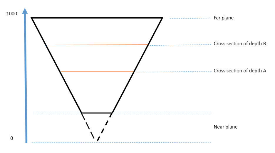
Here is an example of a perspective camera. This is a top view of a perspective camera. The near plane value of the perspective camera is 1, and the far plane value is 1000. The visual range of the camera is from the near plane to the far plane. From the figure, the closer to the near plane, or smaller depth value, the smaller the cross-sectional area, and vice versa. Cross-sections of different areas are finally filled and drawn on the same canvas, and the effect of near-large and far-small will appear. At the same time, different sections will undergo depth detection to realize that objects with a close field of view block objects with a far field of view. The final presentation is a bit similar to the process of taking a photo with a camera, and “shooting flat” all of the three-dimensional things.
Because flat things become three-dimensional, it needs to go through a lot of detailed processing. The most direct point that usually needs to be dealt with here is the deep reduction. According to the presentation of the screen, determine the depth it should be at. Therefore, you can specify the depth when converting the screen touch point to the 3D node world coordinate. The range of depth as shown in the figure above is between the near plane and the far plane, that is, 1-1000, and the normalized value of 0-1 is used in the numerical value. By default, if the depth is not specified, the transformed position of the object is at the near plane position, and if it is 0.5, it is about 500 from the camera.
Next, through the following code, you can easily realize the mutual conversion between screen coordinates and the 3D node world coordinates:
// 3D camera reference
@property(Camera)
camera: Camera = null!;
@property(MeshRenderer)
meshRenderer: MeshRenderer= null!;
onEnable () {
systemEvent.on(SystemEventType.TOUCH_START, this._touchStart, this);
}
_touchStart (touch: Touch, event: EventTouch) {
// Get the camera data in the 3D camera
const camera = this.camera.camera;
const pos = new Vec3();
// 1. Convert 3D node world coordinates to screen coordinates
const wpos = this.meshRenderer.node.worldPosition;
// Convert the world coordinates of the 3D node to screen coordinates
camera.worldToScreen(pos, wpos);
// 2. Convert screen coordinates to 3D node world coordinates
// Get the coordinates of the current touch point on the screen
const location = touch.getLocation();
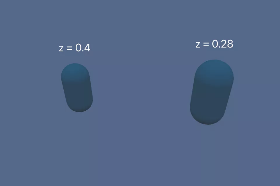
// Note the z value here. The distance between the near plane and the far
// plane is normalized to a value between 0-1.
// If the value is 0.5, then the converted world coordinate value is the position
// of the center tangent plane from the near plane to the far plane of the camera
const screenPos = new Vec3(location.x, location.y, 0.5);
camera.screenToWorld(pos, screenPos);
}
In order to facilitate observation, the far plane of the camera is adjusted to 20 here.
Coordinate conversion between 3D nodes
// 3D node node B local coordinates are converted to 3D node node A local coordinates
const out = new Vec3();
const tempMat4 = new Mat4();
const nodeAWorldMat4 = nodeA.getWorldMatrix();
Mat4.invert(tempMat4, nodeAWorldMat4);
Vec3.transformMat4(out, nodeB.worldPosition, tempMat4);
Convert screen coordinates to UI touch point coordinates
It is still necessary to be clear here that the UI touch point coordinates are the values calculated by the screen touch points according to the UI content area, that is, the UI world coordinate values. The concept itself is not easy to understand, and it seems complicated. Therefore, the engine team will improve this conversion method in subsequent versions and handle it directly through the camera. But the version before 3.4 still needs to be used, so here is a simple summary:
The value obtained by executing event.getUILocation in the callback triggered by the listener node event is that the touch point information is the value calculated by the screen touch point according to the UI content area, which can be directly used to set the world coordinate of the UI node. If there is a design requirement that needs to click on the screen to set the UI node, use this method directly.
const locationUI = touch.getUILocation();
const pos = new Vec3(locationUI.x, locationUI.y, 0);
this.sprite.setWorldPosition(pos);
Coordinate conversion between different nodes of the UI
Unlike Creator 2.x, the size and anchor information of UI nodes are no longer on the node, but each UI node will hold a UITransform component. Therefore, the transformation API between UI nodes is on this component. After obtaining the world coordinates of the UI node and after the screen touch point conversion, it can be converted to the local coordinates of different UI nodes according to the coordinates.
Convert screen touch point coordinates to UI node local coordinates
// Assuming there are two nodes here, node A and its byte node B, click on the screen to
// set the coordinates of node B

// The value of the screen touch point calculated according to the UI content area
const locationUI = touch.getUILocation();
const uiSpaceWorldPos = new Vec3(locationUI.x, locationUI.y, 0);
const nodeAUITrans = nodeA.getComponent(UITransform)!;
// Convert to local coordinates under node A (this value is also relative to the value of node A)
nodeAUITrans.convertToNodeSpaceAR(uiSpaceWorldPos, pos);
nodeB.position = pos;
Coordinate conversion between UI nodes
// Suppose there are two nodes here, node A and node B, they are neither brothers nor
// have a parent-child relationship
const nodeBUITrans = nodeB.getComponent(UITransform)!;
// The final offset value is stored on pos
const pos = new Vec3();
// Get the offset of node A relative to node B
nodeBUITrans.convertToNodeSpaceAR(nodeA.worldPosition, pos);
nodeA.parent = nodeB;
nodeA.position = pos;

// If you want to take a point with a certain offset from itself for conversion,
// you can use the following method:
// Offset 10 units relative to the x-axis of node A
const offset = new Vec3(10, 0, 0);
const nodeAUITrans = nodeA.getComponent(UITransform)!;
// Convert the offset value to world coordinates
nodeAUITrans.convertToWorldSpaceAR(offset, pos);
// Get a point that is offset by 10 units on the x-axis relative to node A, and convert
// it to an offset relative to node B
nodeBUITrans.convertToNodeSpaceAR(pos, pos);
nodeA.parent = nodeB;
nodeA.position = pos;
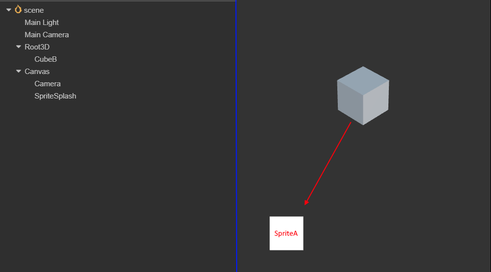
Convert 3D node world coordinates to UI node local coordinates
The principle is to convert the world coordinates of the 3D node to the screen coordinates and then to the local coordinates of the UI node.
// Suppose the 3D node cube, the UI node sprite A,
const out = new Vec3();
const wpos = cube.worldPosition;
// Directly call the camera's conversion interface to complete the entire operation
// Here the value obtained by out is the value "relative to" the offset of sprite A
camera.convertToUINode(wpos, spriteA, out);
const node = new Node();
// The local coordinates are the offset relative to the parent node. Therefore, it is necessary
// to clarify the parent node after the conversion, otherwise the conversion will not be correct.
node.parent = spriteA;
node.position = out;

Radiographic inspection
Before starting to talk about how to use radiographic testing, we must first talk about why there is radiographic testing. When many Creator 2.x developers develop games, they know that there is a “Size” attribute on the node, which represents the size of the node. When clicking on the screen, in most cases the engine calculates whether the node is clicked or not based on the position and “Size” of the touch point and node. The monitoring method uses node events to trigger a callback when the node is clicked. The code is as follows:
this.node.on(Node.EventType.TOUCH_MOVE, this._touchMove, this);
But using this method on the Creator 3.0 3D nodes are not feasible, because the 3D node does not have the so-called “Size” attribute, and the size of the object is different at different depths. Therefore, whether the object is clicked is not simply calculated by the position and “Size”. Here you need to use the ray detection function.
In simple terms, ray detection means that you can specify a starting point A and an ending point B. The engine will emit a ray from A to B, collect and return the respective positions, normals and other information of all objects that collide with the ray, so that you can know Who is the clicked object and how to deal with them respectively. Cocos Creator 3.0 provides 3 ways to create rays:
import { geometry } from 'cc';
const { ray } = geometry;

// Method 1. Via starting point + direction

// Construct a ray starting from (0, -1, 0) and pointing to the Y axis
// The first three parameters are the starting point, the last three parameters are the direction
 const outRay = new ray(0, -1, 0, 0, 1, 0);

 // or
const outRay2 = ray.create(0, -1, 0, 0, 1, 0);

// Method 2. Pass the starting point + another point on the ray

// Construct a ray starting from the origin and pointing to the Z axis
const outRay = new ray();
geometry.ray.fromPoints(outRay, Vec3.ZERO, Vec3.UNIT_Z);

// Method 3. Use the camera to construct a ray emitted from the origin of the camera to a
// certain point on the screen

// Assuming that a camera is already associated here
const cameraCom: Camera;
const outRay = new ray();
// Obtain a ray emitted from a path screen coordinate (0, 0)
// The first two parameters are screen coordinates
cameraCom.screenPointToRay(0, 0, outRay);
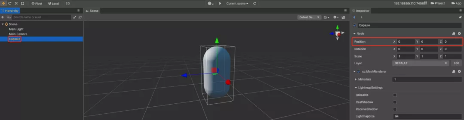
From the above methods of ray creation, if you want to click on the screen to determine whether an object is clicked, method 3 is used. Attentive developers may want to ask, why do I need a camera to determine whether a 3D object is clicked on the screen? I used two cameras to illuminate the same capsule in the scene, which probably explained the relationship clearly.
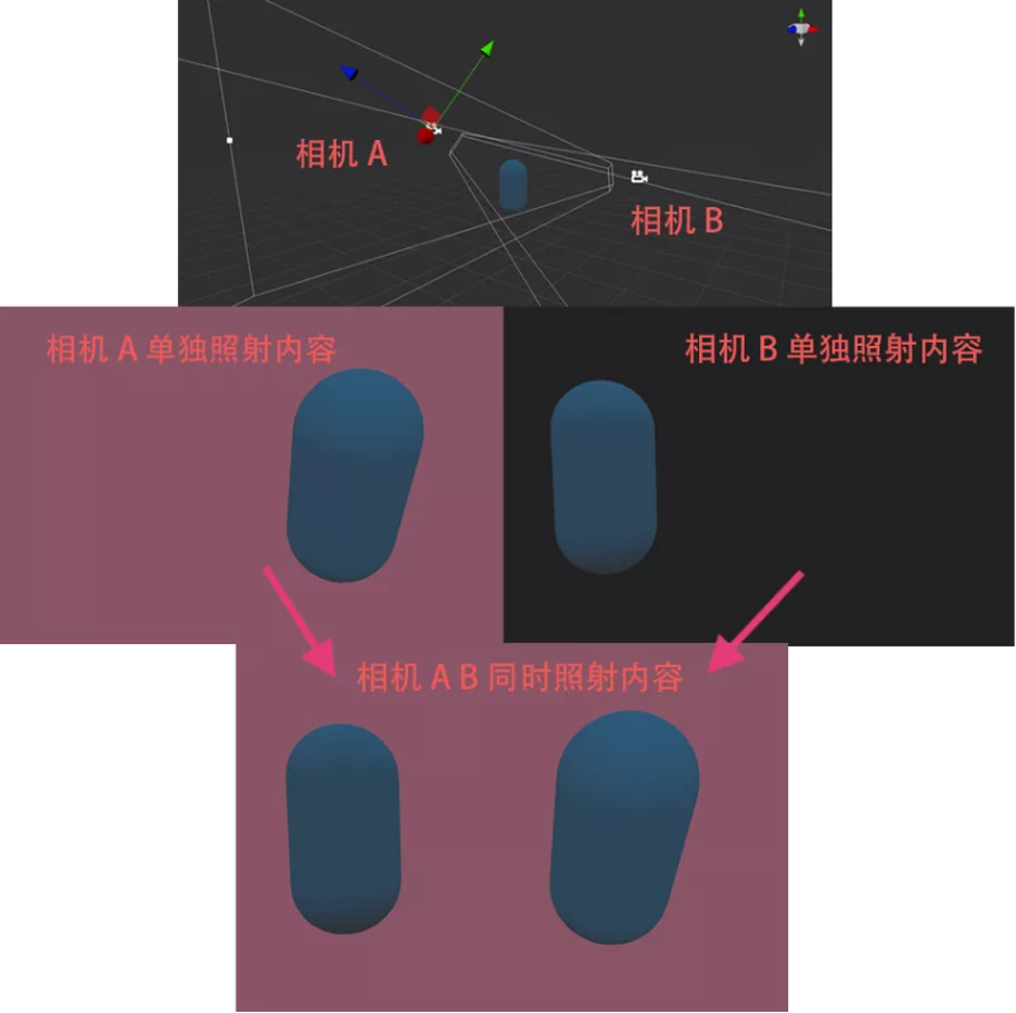
At this point, you will clearly find that even if there is only one capsule in the game scene, if you use two cameras with different shooting angles to illuminate, you will see two objects A on the canvas. At this point, click on area 1. Has the capsule body been clicked? Click on area 2. Has the capsule body been clicked? It is impossible to determine at all.
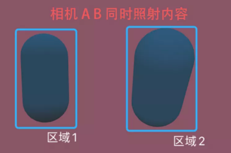
If you specify a camera for judgment, it becomes clearer whether it is right or not. Judging by the angle of view of camera A, click area 1 and the capsule body is not clicked; judging by the angle of camera B, click area 1, and the capsule body is clicked. It can be verified by the following code:
import { _decorator, Component, systemEvent, SystemEventType, Touch, EventTouch, Camera, geometry, MeshRenderer } from 'cc';
const { ccclass, property } = _decorator;
const { Ray, intersect } = geometry;
const { rayModel } = intersect;

@ccclass('TestPrint')
export class TestPrint extends Component {
    // Designated camera
    @property(Camera)
    camera: Camera = null!;

    // Specify the rendering components of the model
    @property(MeshRenderer)
    meshRenderer: MeshRenderer= null!;

    onEnable () {
       systemEvent.on(SystemEventType.TOUCH_START, this._touchStart, this)
    }

    _touchStart(touch: Touch, event: EventTouch){
        const location = touch.getLocation();
        const ray = new Ray();
        // Create a ray connecting the contact position and the camera position
        this.camera.screenPointToRay(location.x, location.y, ray);
        // Obtain the model used to store the rendering data on the rendering component
        // for ray inspection
        const raycast = rayModel(ray, this.meshRenderer.model!);
        // The return value is only 0 and !0, 0 is not detected
        if(raycast > 0){
            console.log('capsule clicked');
        }
    }
}
Note: if the content illuminated by the two cameras needs to be presented on the canvas, then the
ClearFlagsof one of the cameras needs to beDEPTH_ONLY.