
Cocos Shader Series - Draw Shaders With Cocos Creator
Series Chapters
- Basic Introduction
- Build A Triangle
- Draw More Things
- Add Some Texture
- Draw Shaders With Cocos Creator
- Change a Shader with a Texture Map
- Use a Noise Map to Make a Disolve Texture
- Building With WebGL
- Alpha Testing and Blending
- Blend Testing
After understanding the basic principle of WebGL and how to use WebGL rendering, the following few chapters will share with you to find out how this process applied to the Cocos Creator 3.x.
Before we use WebGL to draw out a rectangle, this chapter looks at how to draw the same rectangle Cocos Creator 3.x.
Process overview
In order to facilitate the user’s use and customization, Cocos Creator 3.x encapsulates the internal functions in multiple layers, and users can assemble them according to their needs. Therefore, we only need to assemble the relevant parts. According to the rectangle drawing process, the content can be divided into the following parts:
-
The first is the data preparation part, which means providing vertex data. In this case, we directly provide fixed data. Cocos Creator 3.x provides vertex data in multiple places: 2D rendering components (Sprite, Graphics, etc.), 3D model components (MeshRenderer, SkinnedMeshRendere, etc.), and other methods. Of course, users can also customize the vertex data. Since this part involves the rendering pipeline and the bottom layer of the engine, it is beyond the scope of this chapter. So we won’t discuss this here.
-
The second is the canvas clearing stage, which is related to the camera. Because the game scene is often constructed by many objects, the actual picture presented is only a tiny part of it. The presented part is the part illuminated by the camera. Since our screen canvas has only one section, the camera decides whether to erase the previous content and redraw it or continue drawing based on the original content.
-
The third part is the coloring instruction part, similar to the writing of vertex/fragment text. It is done through Cocos Effect in Cocos Creator 3.x.
Here use the most basic drawing component, Graphics, to draw.
First, create a new scene, create a Canvas node on the hierarchy manager, and create a Graphics node under the Canvas node. Create the script Draw and mount it on the Graphics node and call the Graphics drawing-related interface. Here, how you draw a rectangle:
import {_decorator, Component, Node, Graphics}  from'cc ' ;
const {ccclass, property} = _decorator;

@ccclass( 'Draw' )
export  class Draw extends Component {

    start  () {
        const g = this.getComponent(Graphics) ;
        g.fillRect(0, 0, 200, 150);
    }
}
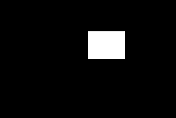
Then, run the preview, and you can see that a pure white rectangle is drawn.
In this process, it has gone through the following stages:
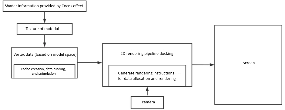
Next, let’s talk about several parts that developers need to care about. All the parts of gl.xxx are processed directly at the bottom layer, so we don’t need to execute it manually unless we need to use customization for the entire process.
Vertex data
In Creator, vertex coordinates originate in model space and eventually need to be converted to screen space. This process requires the following steps:
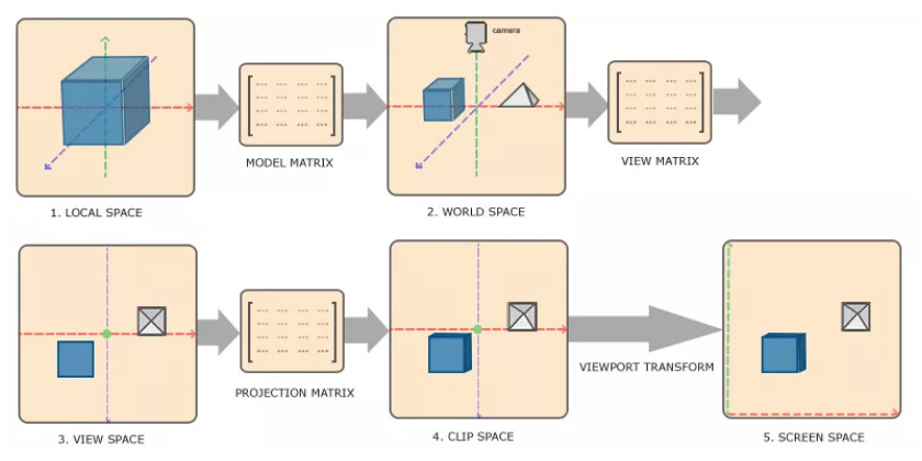
- Local Space - Local coordinates can also be called model coordinates. It can be understood as the coordinates relative to the parent node.
- World Space –The coordinates are a large spatial extent relative to the world origin. It is obtained by combining the model coordinates with the model matrix.
- View Space - It can be understood as converting the world coordinates to the camera space coordinates, and the converted value is relative to the camera origin. It is obtained by combining the world coordinates with the observation matrix.
- Clip Space - The observation coordinates are processed to the range of -1.0 to 1.0, which is the standard device-based coordinates we provide in WebGL. The coordinates that exceed -1 to 1 are eliminated. It is obtained by combining the observation coordinates with the projection matrix.
- Screen Space screen coordinates - This process transforms the coordinates from -1.0 to 1.0 to the coordinates defined by the gl.viewport. The final transformed coordinates will be sent to the rasterizer and converted into fragments.
Therefore, according to the data type, it needs to be converted into the clipping coordinates provided. The graphics provide the model coordinates. Developers who like to explore this further can check the activeMode, _uploadData, and graphics-assembler sections in the graphics.ts in the Cocos Creator engine. Now we can deal with creating the vertex data cache, collecting the drawing data, and binding.
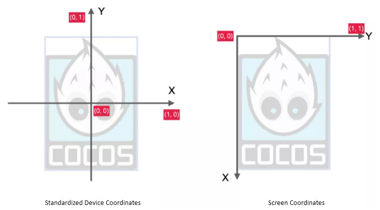
Incidentally, here is the relationship between standard equipment coordinates and screen coordinates. The standardized device coordinates are the x-axis to the right and the y-axis to the up. The values of x and y are both from -1 to 1. The vertices in this range are visible. Otherwise, they are not visible. The screen coordinates are the x-axis to the right, and the y-axis is going down. The range of x and y values are from 0 to the screen width and height. The last step of the matrix transformation is to convert the standardized device coordinates to the screen coordinates and display them on the screen.
Cocos Effect
After having the vertex data, the corresponding Shader text needs to be written. In 3.x, it corresponds to the Cocos Effect. Cocos Effect is a single-source embedded domain-specific language based on YAML and GLSL. The YAML part declares the flow control list, and the GLSL part declares the actual coloring fragments. These two parts complement each other and form a complete rendering process. The engine will execute the corresponding rendering program according to this description. Cocos Effect cannot be used alone. It needs to be used with materials.
Note: if you use VSCode to edit the custom Effect. It is recommended to search and install the Cocos Effect plug-in on VSCode to get code highlighting tips.
We can create a .effect file by right-clicking on the Explorer panel of the editor and selecting Effect.
YAML101
YAML is a serialization language, and it can also be understood as a language that focuses on writing configuration files. Cocos Creator 3.x fully supports the YAML 1.2 standard parser. YAML is fully compatible with JSON syntax, so JSON can also be regarded as a subset of YAML.
YAML is a key-value combination separated by: and spaces.
- All quotes and commas can be omitted
key1: 1
key2: unquoted string

// Note: the space after the colon cannot be omitted
- The number of spaces at the beginning of the line indentation represents the level of data
object1:
  key1:  false
 object2:
  key2: 3.14
  key3: 0xdeadbeef
  nestedObject:
    key4:  'quoted string'

• Start with a hyphen + space to indicate an array element
- 42 is
-  "Double-quoted String"

 // parse the final results are as follows:
{[42 is,  "Double-quoted String" ]}
- YAML can be referenced by & anchor point
object1: &o1
  key1: value1
object2:
  key2: value2
  key3: *o1

// The final analysis result is as follows:

{
    "object1" : {
        "key1" :  "value1"
     },
    "object2" : {
        "key2" :  "value2" ,
        "key3" : {
            "key1" :  "value1"
         }
    }
}
- << means append, similar to inheritance
object1: &o1
  key1: value1
  key2: value2
object2:
  <<: *o1
  key3: value3

// The final analysis effect is as follows:

{
    "object1" : {
        "key1" :  "value1" ,
        "key2" :  "value2"
     },
    " object2" : {
        "key1" :  "value1" ,
        "key2" :  "value2" ,
        "key3" :  "value3"
     }
}
The above part only lists the common writing methods in the development of the Cocos Effect. For more writing methods, please refer to the YAML official website.
Cocos Effect writing
Cocos Effect is mainly composed of two parts:
-
One is the rendering process list compiled in YAML format wrapped by CCEffect. The content listed here mainly involves interaction with the editor (for developers to adjust data in the editor) and data interaction with CCProgram. The core of CCEffect is the Technique rendering technology.
- Technique rendering technology represents a plan to complete a final effect. A plan can be completed by the integration of one or more passes.
- A pass is a GPU drawing, which generally includes a vertex shader and a fragment shader.
- Each vertex/fragment shader must declare its own entry function and provide a return value, where the return value of the entry function will be provided to the entry function of the running platform.
-
The other is a shader fragment based on the GLSL 300es format wrapped by CCProgram.
If you want to draw the target rectangle at the beginning of the article, the content can be as follows:
CCEffect %{
  techniques: -name
  : opaque
    passes: -vert
    : unlit-vs:vert  #here vert corresponds to the vert of CCProgram, which points to the entry function of the rendering platform. For example: WebGL is the main function.
      frag: unlit-fs:frag
}%

CCProgram unlit-vs %{
  precision highp  float ;
  in  vec4 a_position;
  in  vec4 a_color;
  out vec4 v_color;

  vec4  vert  () {
    v_color = a_color;
    return  a_position;
  }
}%

CCProgram unlit-fs %{
  precision highp  float ;
  in  vec4 v_color;

  vec4  frag  () {
    return  v_color;
  }
}%
Note: Cocos Creator uses GLSL es300 format to write Shader fragments. Therefore, all subsequent input and output use the “in” and “out” keywords instead of the old version of “attribute” and “varing.” Of course, if you want to continue to use it, it is still compatible.
When the Graphics component is drawing, it also uses a tailor-made Shader, which can be traced in Graphics.ts. It uses the built-in builtin-graphics. You can in the Explorer Panel → internal-> effects found under. Its content is as follows:
CCEffect %{
  techniques: -passes
  :
    // Determine the vertex and fragment shader. It points to the shader defined by CCProgram.
    -vert: vs:vert
      frag: fs:frag

      // blendState, rasterizerState, and depthStencilState are related to testing and mixing and can be ignored for the time being.
      // The reason for setting here is because the engine provides a set of default testing and mixing configurations, but in 2D, since the depth of the current design no need, therefore, need to modify the configuration manually
      blendState:
        Targets:
        - Blend:  to true
           BlendSrc: One
          blendDst: one_minus_src_alpha
          blendSrcAlpha: One
          blendDstAlpha: one_minus_src_alpha
      rasterizerState:
        cullMode: none
      depthStencilState:
        depthTest:  to false
         depthWrite:  to false
 } %

CCProgram vs %{
  // All floating-point precision definitions in the vertex shader
  precision highp  float ;

  // Introduce the code snippets provided by Creator 3.x
  // cc-global provides projection matrix and observation matrix
  #include <cc-global>
   / / cc-local provides a model matrix
  #include <cc-local>

   // Define the three vertex attribute data a_position, a_color, and a_dist that need input. Among them, a_dist is provided for the anti-aliasing function, so I don't care.
  in  vec3 a_position;

  in  vec4 a_color;
  out vec4 v_color;

  in  float  a_dist;
  out  float  v_dist;

  // Provide the final data value that needs to be passed to the vertex shader main function
  vec4  vert  () {
    vec4 pos = vec4(a_position, 1);

    // Convert model coordinates to clipping coordinates
    pos = cc_matViewProj * cc_matWorld * pos;

    v_color = a_color;
    v_dist = a_dist;

    return  pos;
  }
}%

CCProgram fs %{
  // Low version processing scheme, don’t care.
  #pragma extension([GL_OES_standard_derivatives, __VERSION__ <300])

   precision highp  float ;

  in  vec4 v_color;
  in  float  v_dist;

  // Provide the final data value that needs to be passed to the fragment shader main function
  vec4  frag  () {
    vec4 o = v_color;

    // Don’t care about it here
    #if __VERSION__ <300
      #ifdef GL_OES_standard_derivatives
        float  aa = fwidth(v_dist);
      #else
        float  aa = 0.05;
      #endif
    #else
      float  aa = fwidth(v_dist);
    #endif

    float  alpha = 1.-smoothstep(-aa, 0., abs(v_dist)-1.0);
    o.rgb *= oa;
    o *= alpha;

    return  o ;
  }
}%
Comparing the previous and the next, the part we need almost overlaps with the content needed to draw the rectangle above. There is just one more layer of conversion from model coordinates to clipping coordinates.
Finally, there is still the last part of the content, which is about the camera. When we create the Canvas node, we can see that a Camera node is created by default. The Camera component on the Camera node holds the three properties: ClearFlags, ClearColor, and Rect, and WebGL controls gl.viewport and gl.clear, respectively. In gl.clearColor:
- The SOLID_COLOR mode of ClearFlags requires that the screen content be cleared every frame
- ClearColor requires what color to be filled by default after clearing the screen content
- Rect defines the screen space viewport. The XY value is limited to -1~1, and the wh value is limited to 0~1
So far, we have roughly understood how to obtain the vertex data of a basic drawing component, Graphics, and its Shader content. In the next chapter, let’s analyze the 2D rendering component Sprite that adds texture mapping based on the basic drawing Shader and make some changes to it.
Expand knowledge
All objects in the scene must be within the visible area of the camera before they can be finally rendered. The visual conditions of the camera are divided into two parts:
-
Condition 1: The Visibility of the camera includes the Layer value of the node. For example, the visibility of a 2D camera includes UI_3D and UI_2D, and the layer of the node is DEFAULT, then this node cannot be rendered by the 2D camera.
-
Condition 2: When condition 1 is met, the object needs to be within the line-of-sight frame illuminated by the camera before the object can be rendered.
In the end, all the content is processed by the rendering pipeline into a “flattened” 2D pixel. At this time, it does not mean that such 2D pixels are finally presented. The last stage is the viewport. Assuming that the component of the camera Rect is changed to 0.5 at this time, you can see the comparison of the rendered content before and after:

It can be clearly seen that due to the adjustment of the viewport, only the left half of the screen can present content, so only half of the content illuminated by the camera origin is presented.