
Using Cocos Creator To Give The Eyes A Little “Soul”
After introducing the realization of skin and hair, we enter the last part of the actual character rendering: eyes.
The eye is often the asset with more room to maneuver in a project: It can be straightforward by just using a map, or it can also be very complicated, having an art god manually sculpt every gully of the iris. As a window to the soul, even for stylized cartoon art projects, the importance of eyes cannot be ignored. For the production process of eye art assets, you can refer to this document:
Alfred Roettinger / Realtime Eye
Our target
As before, we will implement the eyeball rendering effect in the engine based on the PBR process of Cocos Creator. Our art resources include a color map representing the “eye white” (scientific name is sclera), a color map representing the “eyes” (scientific name is iris), a normal map, and a MatCap map. Among them, the edge of the iris circle is expressed by the alpha channel of the iris map. In addition, we also need some tricks to show the concealing relationship of the eyeball in the eye socket, which will be explained in detail later.
Laying down the theory
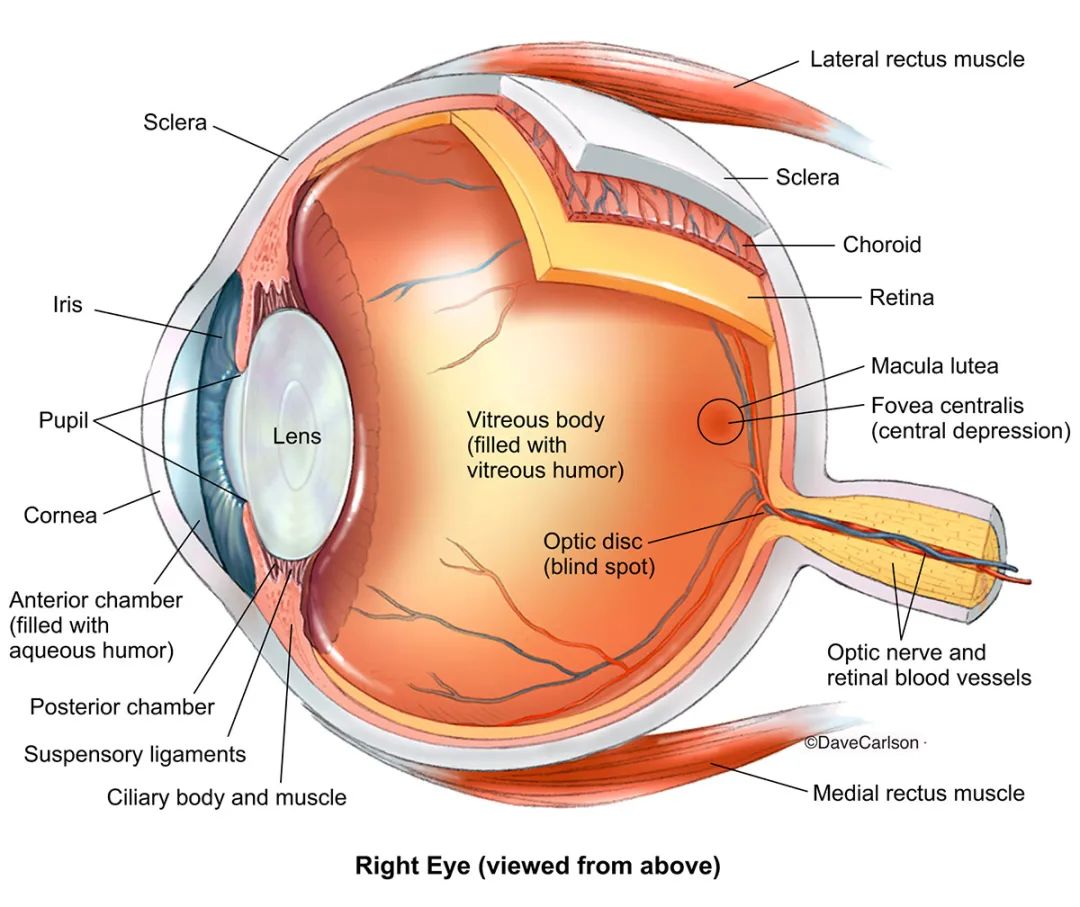
What points do we need to pay attention to the structure of the eye? We still need to ask for the reference picture:
-
The diameter of the iris is approximately equal to the radius of the entire eyeball;
-
The diameter of the pupil is approximately equal to the radius of the iris;
-
The eyeball is not a true sphere but a vacuole structure that protrudes in front of the iris.
First, we need to understand that the eyeball is not a perfectly spherical shape, and there is a circular protrusion directly in front of the iris. This is because there is a vacuole structure directly in front of the iris, and the entire eyeball is wrapped in a transparent sclera, so the eyeball is a streamlined sphere with small protrusions directly in front.
In general, the iris will be our core. We need to focus on the relationship between the iris and the sclera, the pupil, and the vacuole directly in front of it.
UV processing and normalization
In the hair article, we have already talked about UV data, and just like other types of data, it can be arithmetic. The function of UV Tiling that we are familiar with is realized by multiplying UV by a constant. For the iris map, we can also use the same process:
vec2 offsetUV = v_uv * irisSize;
We created a new floating-point parameter irisSize and let it be directly multiplied with the UV data. The result is the same as UV Tiling: the ratio of the iris map on the UV is reduced (when the value of irisSize is greater than 1), and the same iris map is superimposed on the part that is vacated by the UV.
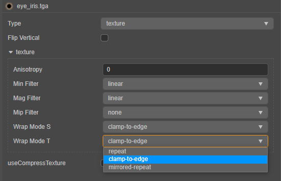
Of course, our eyeballs only need an iris. We want to use constant multiplication method to scale the UV, and do not need to overlay the texture, only need to set the Wrap Mode to clamp-to-edge in the properties of the texture.
With the overlay removed, we have a new problem: the mapping seems to be scaled to the bottom left corner. We need to normalize the coordinate system so that the mapping stays right in the center of the UDIM while we scale the UV.
vec2 offsetUV = (v_uv - 0.5) * irisSize + 0.5;
Our iris is about the same size and position. Next, we need to “push” the iris back into the eyeball to show the relationship between the vacuole and the iris. We can use the parallax map method to achieve this effect.
Parallax map

As shown in the figure above, the gray plane represents the basic grid plane of the object, on top of which the object has a raised surface structure, which is represented by the red curve. When we look at the object in the direction of the V vector in the figure above, we should observe point B on the red curve, and when the protruding surface structure is not present, we will observe point A on the basic grid. In other words: we need the mesh data at point A to achieve the rendering of the height at point B.
We know that the height map expresses the height data of the tangent space of the object. In other words, the tangent space height value (H(A)) of point A can be obtained by mapping. But what about point B? We usually take the height of the tangent space of point A as the numerical weight and zoom in the opposite direction of the observation vector V (from the fragment to the camera), and the position coordinates of B can be roughly obtained. Of course, such calculations cannot be completely accurate, but the effect is acceptable to us.

The method is there. The first step we need to do is to obtain the vector pointing from the fragment to the camera and transform it into the tangent space:
vec3 worldDirPosToCam = normalize(cc_cameraPos.xyz - v_position);

vec3 tangentDirPosToCam = vec3(dot(worldDirPosToCam, v_tangent), dot(worldDirPosToCam, v_bitangent), dot(worldDirPosToCam, v_normal));
We can use the obtained tangent space vector to offset the UV, and read the height information of the tangent space with the offset UV coordinates. In this way, we get the height output of point B at point A:
vec2 parallaxUV( vec3 V, vec2 uv, float iniHeight, float scalar ){

vec2 delta = V.xy / V.z * iniHeight * scalar;

return uv - delta;

}
The above code needs to bring in four parameters: V is the vector from the fragment to the camera in the tangent space we just obtained, and uv is the original uv of the object (that is, the " v_uv"), the scalar is a custom weight parameter, iniHeight is the original height data of the fragment, a texture should provide this data. We only need to use the parallax map to do some simple pixel offsets in our shader, so there is no special height map. We can use any channel of the color map or directly use a constant of 0.5 instead.
Once the function of the parallax map is obtained, we can use it on the iris.
vec2 offsetUV = (v_uv - 0.5) * irisSize + 0.5;

vec4 irisTex = texture(irisMap, offsetUV);

vec2 irispUV = parallaxUV( tangentDirPosToCam, offsetUV, irisTex.r, parallaxScale );

vec3 irisColor = SRGBToLinear(texture(irisMap, irispUV).xyz);
We can use the previously scaled and normalized UV to get the parallax effect of the iris UV, and use this new set of UV to give our iris map, and the result should be similar to the following figure:
As shown in the figure, as the weight value changes, our iris map should be able to “push” or “shrink” backwards along the normal direction. At the same time, we also found that our current parallax map can only achieve one type The approximate effect, as the weight value increases, the effect of parallax will become more and more distorted. Therefore, when we use it, we need to pay attention to controlling the value in a relatively low range.
Complete iris
The processing of the iris is almost done. Next, we need to deal with the pupil.
After completing the parallax of the iris, we proceeded in the same way and normalized the parallax UV we got. The difference is that this time we normalize the UVs, which is equivalent to collapsing all the UVs to the origin of the normalized coordinates. Use this UV sample map to get the effect of stretching the pixels to the center of the coordinates.
The next step is to make a mask to blend the iris and pupil together.
vec2 pupilpUV = normalize(irispUV - 0.5) + 0.5;

float pupilIndex = (1.0 - length(v_uv - 0.5) * 2.0 * irisSize) * (0.8 * pupilSize);

vec2 irisUV = mix(irispUV, pupilpUV, pupilIndex);

vec3 irisColor = SRGBToLinear(texture(irisMap, irisUV).xyz) * irisColor.xyz;
By customizing the parameters irisSize and pupilSize, we can control the size of the iris and pupil, respectively. We can also customize a deflection color irisColor for the iris map to quickly make eyes with different colors.
Now we can put the iris on the eyeball. The basic material of the eyeball uses a scleral map. We only need to superimpose part of the iris on it. The edge part of the iris map is completed with the gradient of the alpha channel. We can use the exponential calculation to control the intensity of the gradient curve, thereby controlling the hardness of the iris edge:
vec3 scleraTex = SRGBToLinear(texture(scleraMap, v_uv).xyz);

float irisEdgeIndex = clamp(pow(irisTex.a, irisEdge), 0.0, 1.0);

vec3 eyeBase = mix(scleraTex, irisColor, irisEdgeIndex) * irisColor.xyz;
Currently, the inherent color information of the eyeball has been obtained. But our eyeballs look no different from directly pasting a color map. The next thing we need to do is to give “God” to the eyeball.
MatCap texture
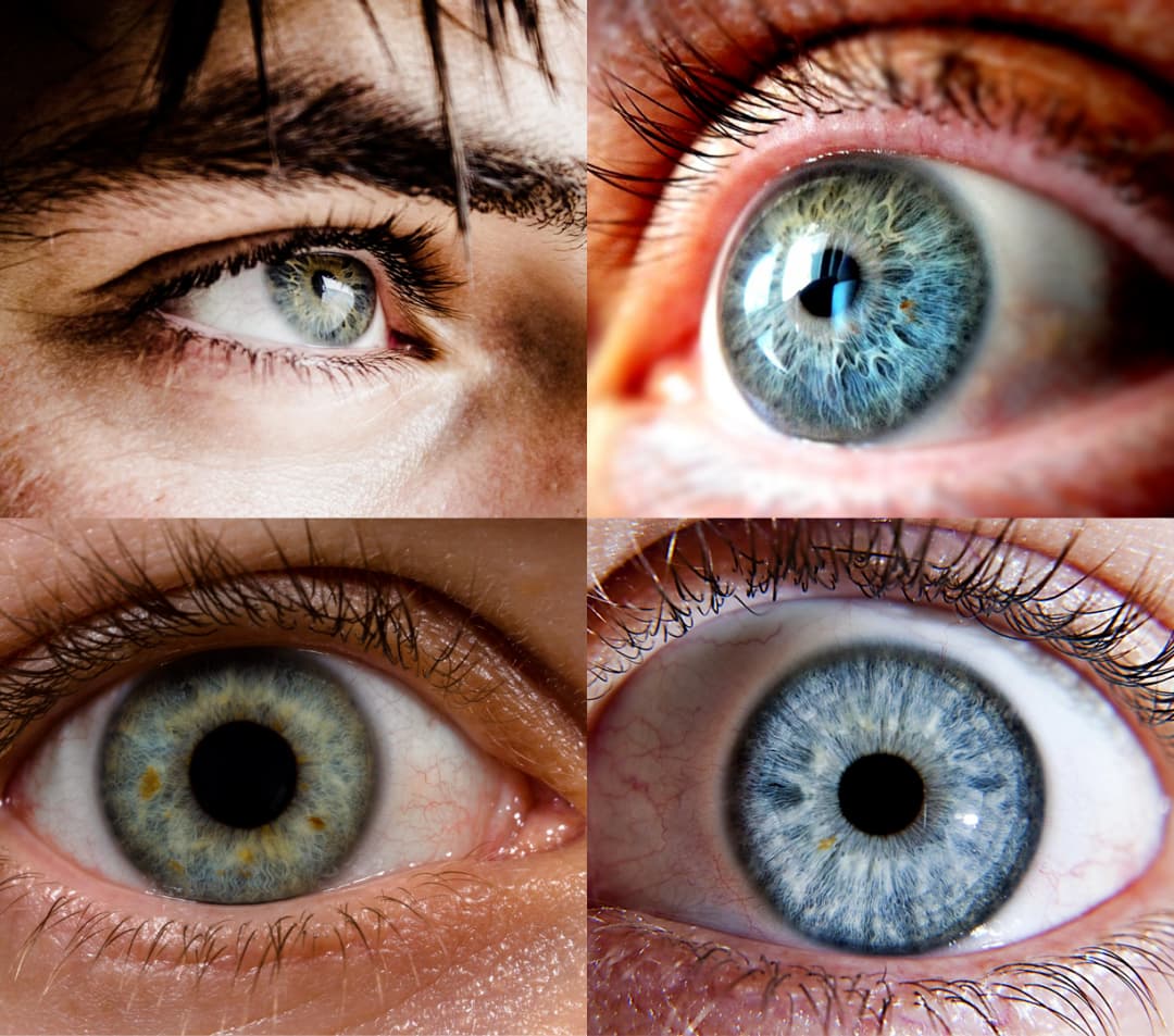
The so-called “god” eyes can be simply be summarized as " eyes with highlights and/or reflections." As shown in the reference picture, the eyes in the upper two reference pictures appear more vivid and energetic, while the lower two look very rigid, like inorganic objects.
However, the character’s eyes in the game do not always reflect the light in the environment. When the environment has certain specific requirements or is viewed from certain angles, the eyes may not have enough highlights or reflections. What’s more, the eyes are important, but after all, they are a small reflecting surface. For this reason, the calculation of the reflected light seems to be a bit outweighed. A common compromise is to use highlights and reflections as textures and permanently “stick” them on the eye’s surface. In this way, no matter the environment and the angle, there will always be stars and lights in the character’s eyes.
The so-called MatCap texture, as the name implies, is a texture that captures (“Cap”) the characteristics of the entire material (“Mat”) into pixels. The MatCap map usually draws a sphere, and the shader will draw the light-dark relationship and high reflection for the entire material based on the light and dark surfaces, highlights, and reflections on the sphere. Art students should be familiar with MatCap-the material used to render millions of polygons in ZBrush uses the MatCap shader. Therefore, MatCap has the advantages of extremely high efficiency and enough to show the relationship between light and shade and texture. At the same time, its shortcomings are also obvious: no matter from which angle it is viewed, the light-dark relationship and high reflectivity of the MatCap material will always remain the same.
Realizing the MatCap material in our shader is also very simple: we know that the characteristic of MatCap is that it always faces the viewing direction. In this case, we can get a set of UVs that are always facing the camera and use it to sample the MatCap texture. We know that the normal data expresses the direction in which the fragments on the surface of the object are directly opposite, so we convert the normal data to the view space and only take the X and Y axis data to get the UV we want:
vec4 matCapUV = (cc_matView * vec4(v_normal, 0.0)) * 0.5 + 0.5;

vec4 matCapUV = (cc_matView * vec4(v_normal, 0.0)) * 0.5 + 0.5;
Once the UV is confirmed, the rest of the work will be complete:
vec3 matCapColor = SRGBToLinear(texture(reflecMap, matCapUV.xy).xyz) * reflecAmt;

vec3 eyeColor = eyeBase + matCapColor;
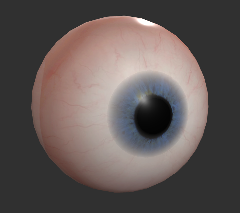
Our shader has been written. Let’s take a look at the effect:
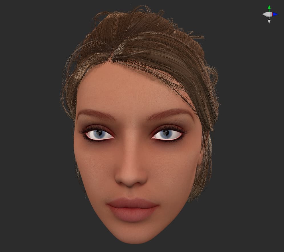
It stands to reason that all the pictures we should refer to have been referenced, the variables that should be considered have been considered, and the work that should be done has been done, but the look in Bai Sensen’s eyes directly creates a sense of sight of a paper man. Especially when viewed from a long distance, the bright white eyes are inexplicably frightening.
This is because the eyes should have a mutual shielding relationship like other parts of the body. Our eyeballs are made separately, so there is no dark part covering the eyelids, so they stand out on the whole face. This is also a common problem with character rendering: we are too familiar with human faces. If there is an abnormal phenomenon on the human face, it will trigger instinctive alertness. And when the other parts are closer to reality, the horror becomes more serious.
If it is a static part, this problem is straightforward: Just bake a piece of AO. But for characters, most of the character’s eyeballs need skeletal animation, so it is obviously not advisable to directly bake AO on the eyeballs. We need to create a new masked model in front of the eyeball model, give it an AO transparency map, and keep it on the model as AO alone. This model will not play any other role except AO, so only a basic Unlit material needs to be given, and no additional resources are consumed. This approach is also the approach chosen by many engines, including UE4.
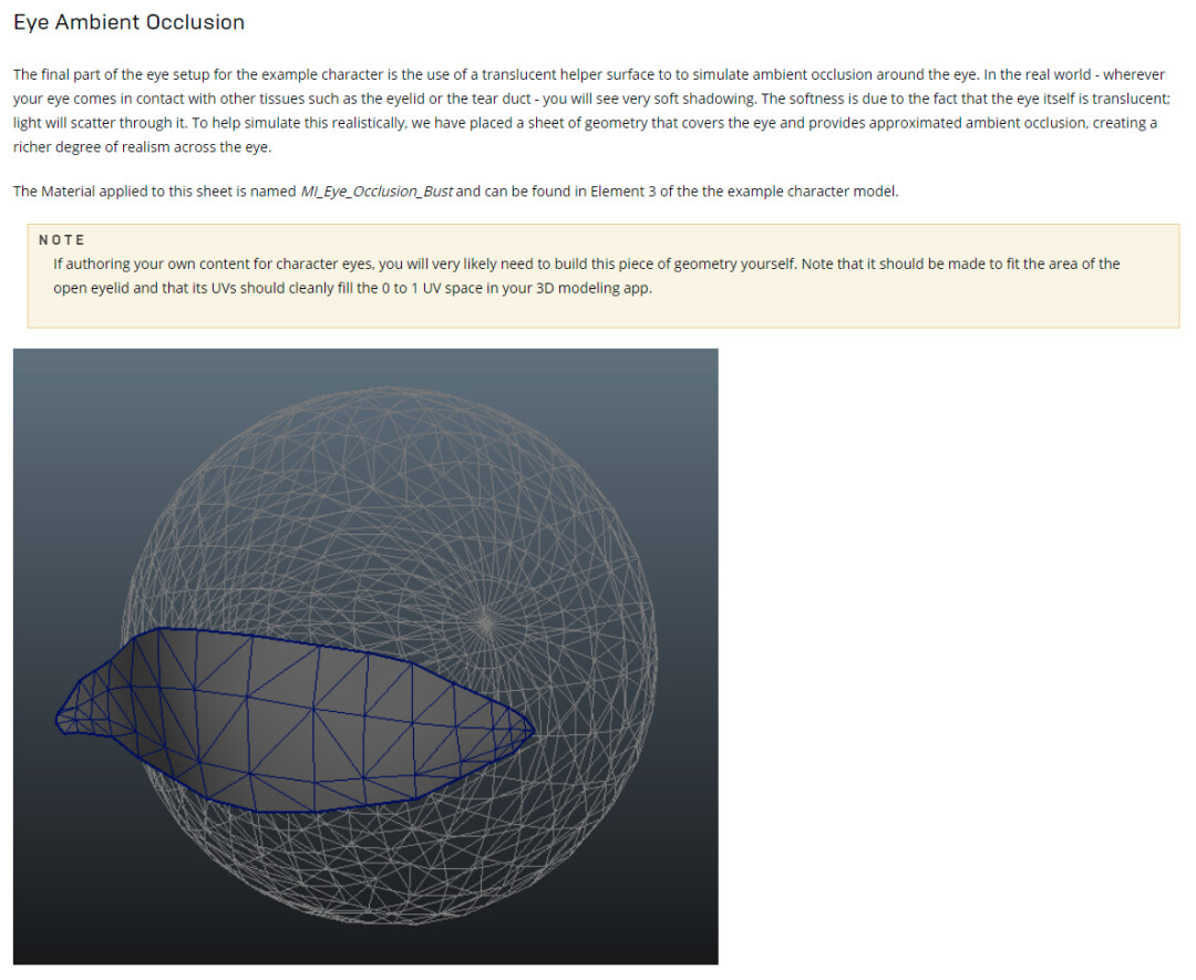
After adding AO, our character’s eyes are much softer, and the connection between eyeballs and eye sockets is more natural.

Series summary
Our exploration of character rendering can be successfully concluded here. In the process of trying to answer each rendering problem, we obtained not only skin, hair, and eyes, but also:
-
Understand the principles of square blur and Gaussian blur, and achieve high-efficiency blur effects.
-
Explore the Diffuse Profile of human skin and use the code to reproduce the data observed in reality.
-
Understand the logic and principles of subsurface scattering and anisotropic highlights.
-
Learn the Kajiya-Kay model of the vertical and horizontal industry for more than 30 years.
-
Try the rendering method of parallax map.
-
Learn and use MatCap textures.
Although we are only modifying the existing shaders in Cocos Creator, I believe you have also discovered that writing your shaders based on Cocos Creator shaders not only saves a lot of GLSL essential work and can be done in one step. Get the basic rendering effect of PBR.