
Yuefu mutual entertainment shares how to achieve a perfect 3D flip effect Cocos Creator using a 2D camera
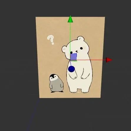
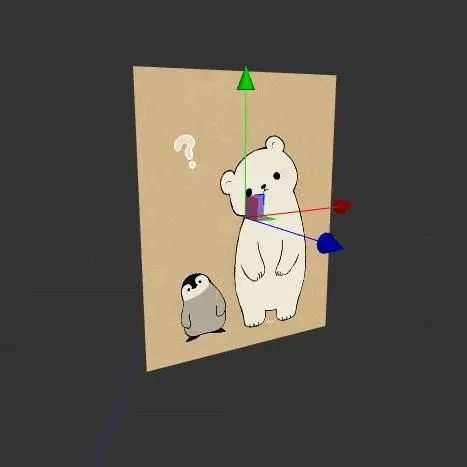
Yuefu Interactive Entertainment has shared the two solutions to achieve 3D flip with a 2D camera. They happily shared it with our group and allowed us to share it with our developers. This is the target effect:

How do you achieve the effect of the above picture? Everyone’s first thoughts were to use a 3D camera, set the 3D node to rotate rotationY, and then move the node.
My first reaction was the same. But, in this case, you have to add a 3D camera, and you need to add a group so that this picture is only rendered by the 3D camera and not rendered by the 2D camera, and at the same time, you need to manage the 3D camera.
Can a 2D camera be used to achieve this effect instead? The answer is, of course: Yes!
First way: Simulate 3D rotation
Since we want to simulate 3D rotation, we first need to know how it moves and the difference between its movement under a 3D camera and a 2D camera?
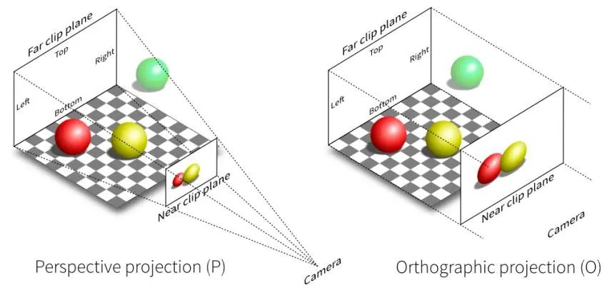
The difference between 3D and 2D cameras is the difference in projection matrix, that is, the difference between perspective projection and orthogonal projection, whether there is an effect of near-large and far-small. We can understand orthogonal projection as the perspective projection of the camera at an infinite distance, far enough to ignore the distance between the screen and the object. Conversely, if you want to simulate perspective projection, you need to assume a camera at a certain distance from the screen.
The process of graph deformation around the Y-axis
- First of all, we assume that it is in the local space coordinate system of the graphic: the origin is at the center of the picture, assuming that the coordinates of a vertex are (x, y, z), and the positive direction of the Z-axis is toward the inside of the screen.
- The graph rotates the angle A around the X-axis, and the vertex coordinates become (xcosA, y, xsinA) at this time.
- Need to request the coordinates of the green point (x2, y2, 0).
Among them,
nis the distance from the camera to the screen, and z is the Z coordinate of the vertex after the change.
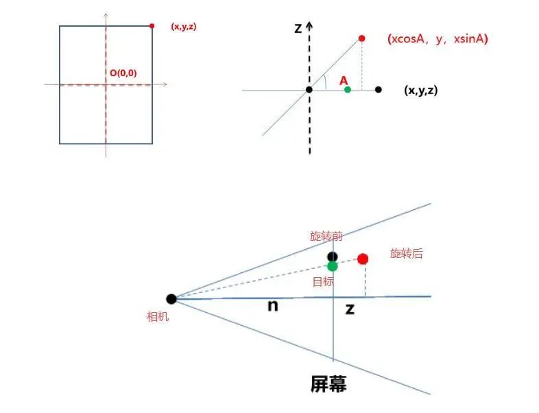
In the above figure, the black point is the point before the rotation, the red point is the point obtained after angle A is rotated, and the green point is the intersection of the point after the rotation and the camera line and the screen.
According to the similar triangle formula, we can easily derive:
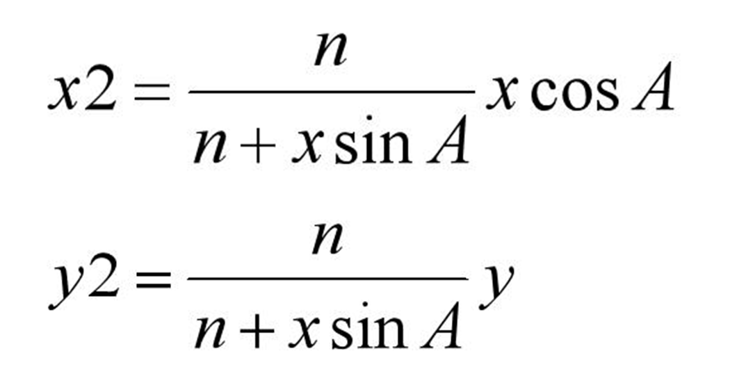
Where (x, y) are the coordinates before transformation, A is the transformation angle, and n is the assumed distance from the projection point to the screen.
We already know the formula for the rotation angle and the coordinates before and after the transformation, so how to modify the vertex coordinates of the picture?
Yes, we can easily think of custom rendering.
Custom rendering
Custom rendering can achieve various effects. There are two methods commonly used at present:
- Create a custom Assembler and modify its value before the vertex data is input to the rendering pipeline.
- Create a custom material and add parameters to the material. This parameter will be passed to the shader as a uniform variable.
This time we adopted the first method: creating a custom Assembler.
Assembler refers to a series of methods for processing vertex data of rendering components. Different rendering components may have different vertex data, several vertices, and filling rules, and different Assemblers may also be used. In the 2D rendering of Cocos Creator we currently use, the Assember2D class is an essential basic class.
The most commonly used modes of cc.Sprite (simple, sliced, tiled, etc.) corresponding to the different Assembler derived classes internally. It is also a quadrilateral node, and different Assemblers can transform it into a different number of vertices to achieve different rendering effects.
Then analyze the bottom Assembler. Our picture uses the simple mode, so we check the simple script and find that the simple script has three functions:
engine/cocos2d/core/renderer/webgl/assemblers/sprite/2d/simple.js
- updateRenderData: call update rendering data function (UV, vertex), mark dirty
- updateUVs: Update UV data
- updateVerts: update vertex data
The updateVerts function only calculates some local image data (calculates the distance between the top, bottom, left, and right sides of the texture in the texture) and then calls the updateWorldVerts function of the parent class Assembler2D to convert the node’s local coordinates to world coordinates and save it to verts (vertex data).
engine/cocos2d/core/renderer/assembler-2d.js
Rewrite the updateWorldVerts of Assembler2D, and the vertex data can be changed by using the calculated vertex data.
Final effect and problem analysis
Get the assembler of the picture node cc.Sprite. Then replace the original vertex coordinates with the recalculated coordinate node (internal). Rewrite the updateWorldVerts method in assembler-2d to use the calculated coordinates. Finally, mark the node’s rendering dirty, to refresh the node’s rendering.
//pseudo code
//Get the assembler to the image node cc.Sprite
let assembler = this.node.getComponent(cc.Sprite)._assembler
// Override the updateWorldVerts method in the assembler to use the calculated coordinates
assembler.updateWorldVerts = function(comp) {
    let points = self.points // use the internal vertex coordinates calculated after changing the angle yourself
let verts = this._renderData.vDatas[0] //vertex data
let matrix = comp.node._worldMatrix;
    let matm = matrix.m //the 4*4 transformation matrix
let a = matm[0], b = matm[1], c = matm[4], d = matm[5],
    tx = matm[12], ty = matm[13];
    //Matrix multiplication:
    //x' = ax + cy + tx
    //y' = bx + dy + ty
    // left bottom
    verts[0] = a*points[0] + c*points[1] + tx
    verts[1] = b*points[0] + d*points[1] + ty
   // right bottom
    verts[5] = a*points[2] + c*points[3] + tx
    verts[6] = b*points[2] + d*points[3] + ty
    // left top
    verts[10] = a*points[4] + c*points[5] + tx
    verts[11] = b*points[4] + d*points[5] + ty
    // right top
    verts[15] = a*points[6] + c*points[7] + tx
    verts[16] = b*points[6] + d*points[7] + ty
}
// Dirty the node's render marker to refreshen the node's rendering
this.node.getComponent(cc.Sprite)._vertsDirty = true
this.node._renderFlag |= 1 << cc.RenderFlow.FLAG_LOCAL_TRANSFORM
The final effect is as follows:

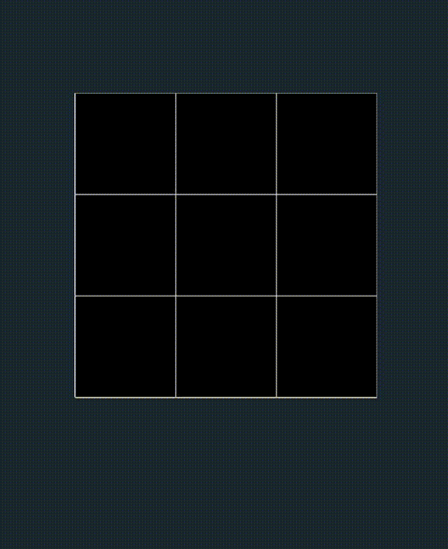
It looks fine, but there seems to be some distortion in the image when slowed down. Let’s use the nine-panel image for comparison, and sure enough, the movement is distorted, and the image is distorted along the diagonal:
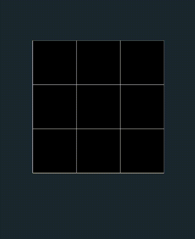
Why is it distorted? This is because we have modified the 2D point positions to the 3D vertex position data to warp the graph to the style we want, but the UV coordinates of the vertices are still 2D and have no depth. The problem here is that we are interpolating the UV coordinates incorrectly. 3D UV interpolation is not necessarily linear unless the Z-coordinates of the vertices are all the same.
This approach is not desirable. Let’s go back and think about the implementation. Why does the 2D camera display differently from the 3D camera? We learned that the projection is different in our previous attempts, so is it possible to modify the camera projection?
Attempt two: Modify camera projection
If you want to modify the camera projection, you need to know how the projection affects the node’s rendering, so we analyzed the default texture of the picture.
Default texture analysis:
Resources/static/default-assets/resources/effects/builtin-2d-sprite.effect
(Analyze only to vertex shader)
CCProgram vs %{
  precision highp float;// Defines the precision of a floating-point type as high precision
  // Introduce cocos' built-in shader variables - engine/cocos2d/renderer/build/chunks
  #include <cc-global>
  #include <cc-local>

  in vec3 a_position;//vertex coordinates
  in vec4 a_color;//Vertex Color
  out vec4 v_color;// The color values that will be output by the vertex shader fragment

  //Whether to use mapping (mapping will input and output texture coordinates if used/)
  #if USE_TEXTURE
  in vec2 a_uv0;
  out vec2 v_uv0;
  #endif

  void main () {
    vec4 pos = vec4(a_position, 1);
    //Whether an image template is not used as a mask
    #if CC_USE_MODEL
    pos = cc_matViewProj * cc_matWorld * pos;
    #else
    pos = cc_matViewProj * pos;
    #endif

    #if USE_TEXTURE
    v_uv0 = a_uv0;
    #endif
    v_color = a_color;
    gl_Position = pos;
  }
}%
Looking at the source code vertex shader code snippets, we find that the vertex coordinates are closely related to cc_matViewProj and cc_matWorld. What does cc_matViewProj and cc_matWorld in the image Shader actually mean?
By looking at the official [built-in shader variable] document, we found that cc_matWorld is a transformation matrix that converts the coordinates of a vertex to world coordinates, and cc_matViewProj is a transformation matrix from model coordinates to perspective. Then if you want to modify the camera projection, you must finally modify the value of cc_matViewProj.
I know the value to be modified, but how did this value come from?
I have to praise here, and this is the benefit of the open-source engine- check the source code!
cc_matViewProj =>
view._matViewProj =>
camera.extractView(view, width, height) =>
Mat4.copy(out._matViewProj, _matViewProj)=>
this._calcMatrices(width, height)
We kept going from one parameter to another parameter, from one function to another function. Finally, We found that the camera has different matrix calculations according to a perspective projection. We finally got the _matViewProj we want, the view projection matrix. Now let’s understand how the camera’s perspective matrix is calculated.
Camera script analysis
engine/cocos2d/renderer/scene/camera.js
_calcMatrices (width, height) {
    // View matrix (since this node is a camera node, the inverse matrix of the world matrix of the camera node is the viewport matrix)
    this._node.getWorldRT(_matViewInv);
    Mat4.invert(_matView, _matViewInv);

    //Perspective Matrix
    let aspect = width / height;
    if (this._projection === enums.PROJ_PERSPECTIVE) { //perspective projection
      Mat4.perspective(_matProj,
        this._fov,  // Vertical view size (radian value)
        aspect,     //Aspect ratio
    this._near, //near plane distance
        this._far   //far plane distance
      );
    } else {  //orthogonal projection
      let x = this._orthoHeight * aspect;
      let y = this._orthoHeight;
      Mat4.ortho(_matProj,
        -x, x, -y, y, this._near, this._far
      );
    }

    // _matViewProj = View projection matrix (view matrix * projection matrix)
    Mat4.mul(_matViewProj, _matProj, _matView);

    // _matInvViewProj = The inverse matrix of the view projection matrix
    Mat4.invert(_matInvViewProj, _matViewProj);
  }
Change the cc_matViewProj of the target image to the vp value of the perspective projection (perspective matrix * view matrix and convert it into an array) to achieve the effect of 3D projection with a 2D camera.
Knowing how to modify the projection matrix and where to write the modified matrix, how should we pass the custom parameters into the shader now? The answer is custom materials!
Custom material
Right-click in the resource manager to create a new effect and create a new Material reference to the corresponding effect (the explanation of the relationship between the Material and the effect can be found in the official Cocos Creator - Material Resources documentation.
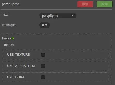
We only need to declare a 16-bit array variable (such as mat_vp) in the properties of the newly created Effect file and then get the material of the image and convert our calculated view projection matrix into an array value and pass it into the custom material, material.setProperty(mat_vp, arr) will do.
Operation steps and final results
-
Create a new effect script and the corresponding material, and mount the material on the picture.
-
Customize a parameter in effect to store our calculated matrix array and use it in the vertex shader.
//pseudocode
// Create a new "mat_vp" parameter in the effect script to store the calculated pivot matrix
properties:
  mat_vp: {value:[0.0,0.0,0.0,0.0,0.0,0.0,0.0,0.0,0.0,0.0,0.0,0.0,0.0,0.0,0.0,0.0]}
  texture: { value: white }
 //pseudocode
 // Using our custom parameters in the vertex shader
 CCProgram vs %{
  void main () {
    #if CC_USE_MODEL
    pos = mat_vp * cc_matWorld * pos;
    #else
    pos = mat_vp * pos;
    #endif
    gl_Position = pos;
  }
}%
- Create a new class, calculate the (perspective matrix * view matrix) and convert it into an array.
export class PerspectiveCamera {
    public static setVPMatToNode(node:cc.Node, cameraNode: cc.Node) {
        // Calculate the width/height of the device
        let aspect = cc.view._viewportRect.width / cc.view._viewportRect.height
        // Get the view matrix matView
        let matView:any = cc.mat4()
        let matViewInv:any = cc.mat4()
        // Get the camera's view matrix
        cameraNode.getWorldRT(matViewInv)
        // Matrix inversion
        cc.Mat4.invert(matView, matViewInv)
        // Get the pivot matrix
        let matP:any = cc.mat4()
        let fovy = Math.PI / 3
        // Calculating the perspective projection matrix
        cc.Mat4.perspective(matP, fovy, aspect, 0.5, 1500)
        //VP = Pivot Matrix*View Matrix
        let matVP = cc.mat4()
        cc.Mat4.mul(matVP, matP, matView);
        let arr = []
        // Matrix to array.
        cc.Mat4.toArray(arr, matVP)
    }
}
- Pass the calculated array into the shader script.
// Get image texture
let material = node.getComponent(cc.Sprite).getMaterial(0)
// Pass the calculated values to the custom "mat_vp" parameter (arr is the pivot matrix * view matrix and transpose the array)
material.setProperty("mat_vp", arr)
- Then set the node as a 3D node, and rotate the
RotationYof the node according to the required angle.
// Finally, changing the rotationY value of the node is all it takes
this.node.rotationY = The angle you want to rotate****
The final effect is as follows:

Perfect!
Extension link
Cocos Creator - Built-in shader variable
Cocos Creator - Material Resources
Yuefu Notes
This article was first published on the official account of Yuefu Notes, where the Yuefu team shares their front-end, back-end, and platform-related technical experience and innovation results on WeChat.