
Hardcore Game Engine Magic! Implement 2D&3D Textured Drawing
The Graphics components provide us with a series of drawing interfaces, but sometimes to achieve some special needs, it is inevitable that we need to build something ourselves. Today, I will share with you some simple functions using graphics. This will achieve:
- 2D textured drawing of various paths and other effects.
- 3D can draw various paths, graphics, and other effects with a high degree of freedom.
Specifically, these can be used in the real-time drawing of character path lines in games, brushes that can be used to draw with unique textures, real-time generation of 3D objects that players want in 3D games, or generating 3D objects with high degrees of freedom in gameplay, etc.
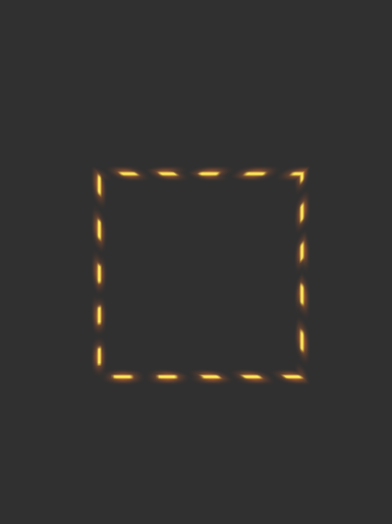
2D effect preview
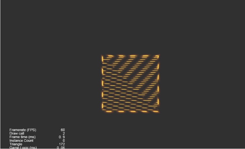
3D effect preview
The engine version used this time is Cocos Creator 3.4.1. The following is my own modification. The same idea can also be used for the modification of other components.
1. 2D textured
Although the engine source code is neat and straightforward, its documentation still looks cloudy. What should I do? There is no shortcut, and when I looked at the folders by category, I really didn’t have the difficulty I’d imagined (because I had seen the code of a super-coupled project before, it was a hell-level reading difficulty, and the logic of the code was too exhaustingly complicated.)
Reading the engine source code can help you know the graphics drawing principles:
- Implement drawing components and collect drawing information through various interfaces:
graphics.ts - Implement the vertex rendering data assembler:
graphics-assembler.ts - The storage and processing of drawn path points are implemented in
impl.ts
So, how to make the change? I thought of the method of inheriting + overloading the graphics components:
- The
graphicscomponent’s_flushAssemblermethod is where the vertex rendering data assembler is obtained so that the vertex data rendering assembler can be overridden in this method. - If you want to add texture, the
shaderneeds line length, line length, and line width, which can form uv coordinates to get the texture’s pixels. - In the
onLoadmethod,impl.tsreplace the waypoint storage processor with your implementation of the waypoint storage processor.
Got the idea? Get to work!
First, inherit the graphics component, and then overload the _flushAssembler method according to the source code. Considering that the assembler method is that an object is not a class and cannot be inherited, I simply create a new object without doing it, shamelessly named it superGraphicsAssembler, and assign all the methods of the original assembler to the new assembler.
Because our purpose is to add line length data to the vertex data of the component, we need to do things in the _flattenPaths method.
First, rewrite it (in fact, copy the source code of this method and change it). As for the place where the error will be reported, the import should be imported. If it cannot be imported, declare its type in __private._cocos_2d_assembler_graphics_webgl_impl__Impl this way. If that doesn’t work, any type will suffice.
If there is a need to extract the type new of the object and it cannot be imported from the engine, rewrite the class. For example, const dPos = new Point(p1.x, p1.y); in this line, you can copy the engine’s Point class and rename Point2 to it. By the way, add your own lineLength line. Then, input pts[0]["lineLength"] = lineLength; this way, the line length from the initial point to each point is calculated and assigned to the path point data, and when the vertex data is assembled, the same method can be used to obtain it.
At this point, our path points have all brought the line length data, but it is useless to have path points alone. This data needs to be added to the vertex data and sent to the shader for use. So we set our sights on the Assemble Wired Vertex Rendering Data _expandStroke method. Copy it over and change it, and pass an additional parameter to the place where the set vertex data _vSet method lineLength - yes, the line length we just took out from the path point object.
But then we found that the _vSet data set in the method is achieved by setting the element value of the corresponding subscript in the buffer array, so we need to modify the vertex data format so that the buffer of the stored data after adding new members can be accessed by shaders downstream of the rendering pipeline understand. Look it up, and its vertex data format is defined in the graphics.ts file:
const attributes = vfmtPosColor.concat([
new Attribute('a_dist', Format.R32F),
]);
Jump in and take a look. It turns out to be: vfmtPosColor
export  const vfmtPosColor = [
new Attribute(AttributeName.ATTR_POSITION, Format.RGB32F),
new Attribute(AttributeName.ATTR_COLOR, Format.RGBA32F),
];
Each entry in the buffer array is a new one more data. The a_position three array elements of 32-bit are one data, the one data, and one array element of 32-bit newly added in is one data. I believe that some developers have discovered the pattern. float a_color float graphics float a_dist
Let’s copy it over and add one more piece of data:
const attributes2 = UIVertexFormat.vfmtPosColor.concat([
new gfx.Attribute('a_dist', gfx.Format.R32F),
new gfx.Attribute('a_line',gfx.Format.R32F),
]);
Yes, it is the line length; a 32-bit float element is enough. Then we assign all attributes of the code used in the source code to our own definition attributes2, and do the same for the code that uses these two:
const componentPerVertex = getComponentPerVertex(attributes);
const stride = getAttributeStride(attributes);
What are these two for? Jump in the source code to look at the generating function to know is the total number of occupied elements and the total byte length of a single vertex data.
Now let’s go back to the _vSet function. At this time, we found that after modifying the vertex data format, there is a space to put the line length data buffer in, so we have vData[dataOffset++] = distance; add a line below vData[dataOffset++] = lineLong;.
In addition, _vSet after the function is changed, all the places where the _vSet function must be changed to add the line length data, so we _vSet copy all the methods in the source code that use the function and add the line length parameter.
This time it was perfect!
Can you try it now? No, don’t worry, I just changed the upstream of the rendering pipeline to make the pipe thicker, and the downstream pipe is not compatible yet and will burst. Based on the principle of due diligence, copy graphics and create a new one arbitrarily named pathLine, emulated in the shader’s vertex function:
in float a_dist;
out float v_dist;
Also, write:
in float a_line;
out float v_line;
This a_line is the shader pipeline that takes over the a_line line (like a water pipe) and out, which flows into the next water pipe (fragment shading function). Of course, there are two water pipes in the middle of these two water pipes. Doing some undertaking (the vertex data is connected to triangles, and rasterization cuts each triangle into countless pixel grids), the middle of these two water pipes do not need to be ignored, as long as you know their functions. Then, in the fragment shader pipe, the line width and line length are composed of uv coordinates to get the pixels of the texture:
vec2 uv0 = vec2(v_line,(v_dist + 1.)/2.);
uv0.x = fract(uv0.x);
uv0.y = fract(uv0.y);
o *= CCSampleWithAlphaSeparated(texture1,uv0);
Where did this texture come from? Add it now:
properties:
texture1: { value: white }
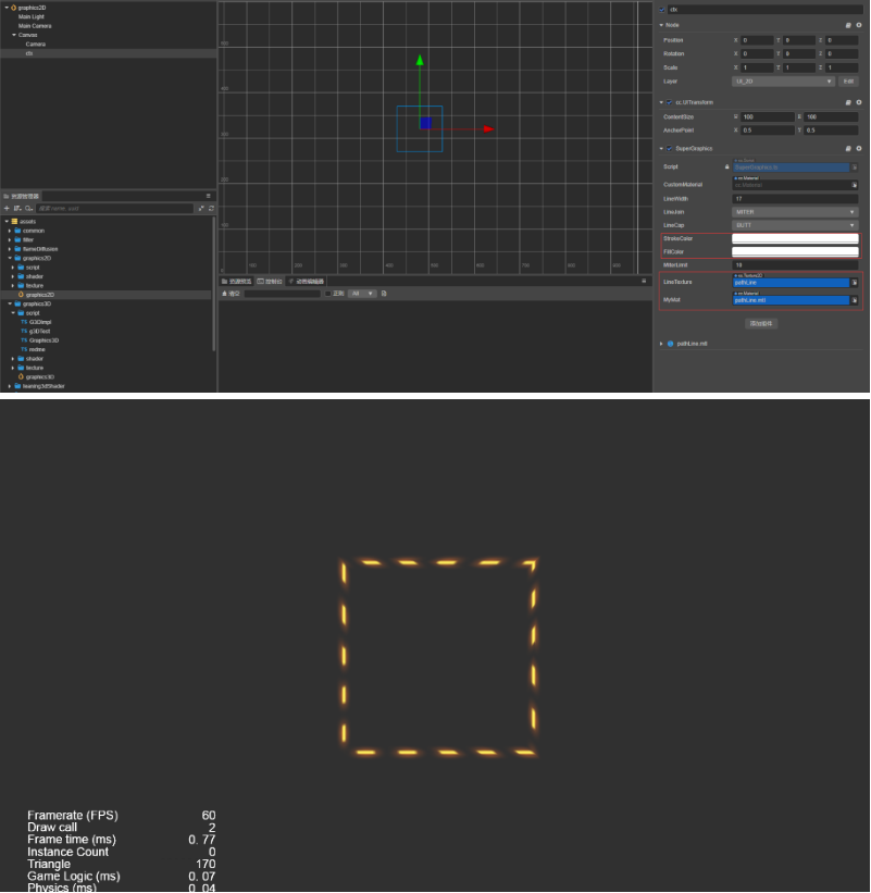
Add it to the fragment shading water pipe, uniform sampler2D texture1; and then add the place to set the material and texture SuperGraphics in :
@ccclass ('SuperGraphics')
export  class SuperGraphics extends Graphics {
@property (Texture2D)
lineTexture:Texture2D = null ;
@property (Material)
myMat:Material = null ;
onLoad(){
if ( this .lineTexture){
this .lineWidth = this .lineTexture.height;
lineC = this .lineWidth/ ( this .lineTexture.height * 2 * this .lineTexture.width);
}
if ( this .myMat){
this .setMaterial( this .myMat, 0 );
if ( this .lineTexture)
this .getMaterial( 0 ).setProperty(“texture1”, this .lineTexture);
}
  super .onLoad();
}
onEnable(){
if ( this .myMat){
this .setMaterial( this .myMat, 0 );
if ( this .lineTexture)
this .getMaterial( 0 ).setProperty("texture1", this .lineTexture);
}
}
Final effect
Note: The current code will cause display exceptions if drawn using the close, lazy method can be used without closing.
2. 3D with or without texture
With the previous experience, the next upgrade experiment will change the graphics magic to 3D.
We need to add a z coordinate, then graphics add the interface moveTo3d, lineTo3d, etc., on the previous basis, and then imitate the source code to impl.ts, copy, and rewrite it add the coordinates to the places with 2D z coordinates.
In our Graphics3D component, assign the data of onLoad and the original impl object to the new G3DImpl object, and then copy all the code in the source code that uses the impl object to use its own G3DImpl object.
Since the a_position is always a z coordinate storage location in the vertex data structure, the vertex data structure with the line length added above is used. Finally, you can enjoy using programs to draw high-degree-of-freedom 3D drawings!
- The material attached to the 3D drawing component can check the depth writing and depth testing, and the effect is better.
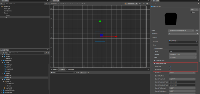
- 3D drawing components can be textured or untextured
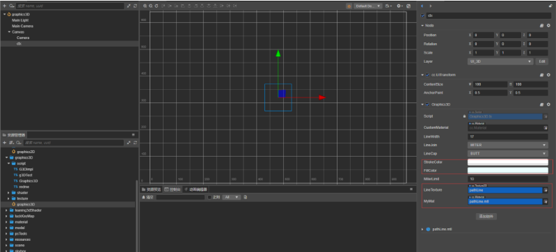
Final effect

Complete source code
Forum post