
Creating Custom Vertex Format That Allows Custom Rendering
Thanks to another star writer from our Chinese forums, GT, for their post. We translated to English to help you on your journey of game development.
Background
Custom rendering can achieve many cool shader effects. There are two commonly used methods:
-
Create a custom material and add parameters to the material. These parameters will be passed into the shader as a uniform variable.
Because the rendering batch requires the same material parameters, if a large number of objects use custom materials and the material parameters are different, batch rendering cannot be performed. One object occupies one draw call.
-
Create a custom assembler and modify its value before the vertex data is input to the rendering pipeline.
This method is more flexible. If you need to enter more custom parameters, the standard vertex format is not enough.
This article introduces another method, which allows the shader to obtain custom parameters, that also allows custom materials to be rendered in batches. This approach is a custom vertex format. This all starts with the assembler.
Detailed Assembler

The assembler is the core class that implements the related functions of this article.
Note: please refer to the Custom Renderer documentation for many important details. (Chinese only)
The assembler must define the updateRenderData and fillBuffers methods. The former needs to update and prepare vertex data, and the latter is to fill the prepared vertex data into the VetexBuffer and IndiceBuffer.
In 2D rendering, the Assember2D class is an important basic class. The most commonly used modes of cc.Sprite (simple, tile, 3x3 grid) correspond to different assembler derived classes internally. It is also a quadrilateral node, and different assemblers can transform it into a different number of vertices to achieve different rendering effects.
The simple mode is a regular quadrilateral with four vertices.
In tiling mode, the assembler “breaks up” the nodes according to the number of repetitions of the texture, which is equivalent to generating a quadrilateral for each repetition.
In the 3x3 grid mode, the assembler splits the node into nine quadrilaterals, and each quadrilateral corresponds to a grid on the texture.
Interpretation of fillBuffers source code
Assembler2D looks at how to achieve fillBuffers. Source code.
fillBuffers (comp, renderer) {
// If the world coordinates of the node change, recalculate the vertex data from the world coordintes of the current node.
if (renderer.worldMatDirty) {
this.updateWorldVerts(comp);
}
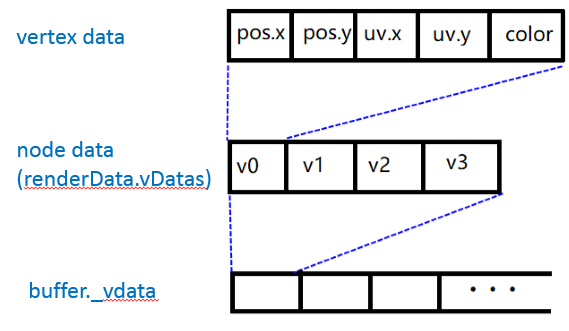
// Get prepared vertex data
// vData contains pos, uv, color data
// iData contains the vertex index data after triangulation
let renderData = this._renderData;
let vData = renderData.vDatas[0];
let iData = renderData.iDatas[0];
// Get vertex buffer
// The getBuffer() method will be overloaded by us later to get a buffer that supports custom vertex formats
let buffer = this.getBuffer(renderer);
// Get the offset of the vertex data of the current node corresponding to the final buffer.
// It can be understood that the data of the current node and other nodes in the same format will be appended to this large buffer in order.
let offsetInfo = buffer.request(this.verticesCount, this.indicesCount);
// fill vertices
let vertexOffset = offsetInfo.byteOffset >> 2, vbuf = buffer._vData;
// Copy the prepared vData to VetexBuffer.
// It will be judged here that if the buffer cannot fit, the vData will be truncated.
// Usually there is no such a situation that it cannot be installed, because enough space will be allocated in buffer.request; if it does, the current component can only be rendered partially.
if (vData.length + vertexOffset > vbuf.length) {
vbuf.set(vData.subarray(0, vbuf.length - vertexOffset), vertexOffset);
} else {
vbuf.set(vData, vertexOffset);
}
// Copy the prepared iData to IndiceBuffer
let ibuf = buffer._iData, indiceOffset = offsetInfo.indiceOffset, vertexId = offsetInfo.vertexOffset;
for (let i = 0, l = iData.length; i < l; i++) {
ibuf[indiceOffset++] = vertexId + iData[i];
}
}
FAQ
Q: Why do we need to prepare the vertex data instead of filling the buffer after the direct calculation in the fillBuffer() method?
A: Because fillBuffer() is called in every frame, it is a hot code, and efficiency needs to be paid attention to. But the vertex data is ot updated every frame; it can be pre-calculated.
Q: Do I need to modify the fillBuffer() method to implement a custom vertex format?
A: No, fillBuffer() is a simple byte stream copy. It only cares about the data length, not the data content.
Q: What content does the vertex data contain? How to calculate?
A: see below
Vertex data format description
The most commonly used vertex format is vfmtPosUvColor, used by Assembler2D by default. Vertext Format Example
var vfmtPosUvColor = new gfx.VertexFormat([

    // The world coordinates of the node, occupying 2 float32

    { name: gfx.ATTR_POSITION, type: gfx.ATTR_TYPE_FLOAT32, num: 2},

    // The texture uv coordinates of the node, occupy 2 float32

    // If the node uses an independent texture (not combined), the uv value here is usually 0 or 1.

    // The texture of the combined image, where the uv corresponds to its relative position in the atlas, and the value range is within [0,1].

    { name: gfx.ATTR_UV0, type: gfx.ATTR_TYPE_FLOAT32, num: 2 },


    // The node color value can be set on the cc.Sprite component. 4 uint8 = 1 float32

    { name: gfx.ATTR_COLOR, type: gfx.ATTR_TYPE_UINT8, num: 4, normalize: true },

]);
The corresponding relationship between the vertex format and the attribute variable of the shader vertex shader is as follows.
CCProgram vs %{

  precision highp float;

  #include <cc-global>

  #include <cc-local>

// Corresponding to the 3 fields in the vfmtPosUvColor structure

// Note that here a_position is of vec3 type, but vfmtPosUvColor has customized 2 float lengths for it. So a_position.z = 0

  in vec3 a_position;     // gfx.ATTR_POSITION

  in vec2 a_uv0;          // gfx.ATTR_UV0

  in vec4 a_color;        // gfx.ATTR_COLOR

// ...

void main () {

      // ...

  }

}%
Some commonly used attribute variable names are defined in enums.js.
The developer can customize the variable name attribute, only the format of the vertex shader and the variable name matching can.
Take a look at the corresponding relationship between attributes and vertex formats in Assembler2D. Source code
cc.js.addon(Assembler2D.prototype, {

    // vfmtPosUvColor structure occupies 5 float32
    floatsPerVert: 5

    // A quadrilateral with 4 vertices
    verticesCount: 4

    // A quadrilateral is divided into 2 triangles according to the diagonal, 2*3 = 6 vertex indexes
    indicesCount: 6,

    // The value of uv is counted from 2 in the subscript in the vfmtPosUvColor structure
    uvOffset: 2,

    // The value of color is counted from 4 in the vfmtPosUvColor structure
    colorOffset: 4,
});
Vertex data calculation
After understanding the vertex format above, the vertex data is nothing more than calculating the values of pos, uv, and color.
In assembler we use updateVerts(), updateUVs(), and updateColor() as ways to prepare these values, and they are temporarily stored in the array using assembler’s own distribution.
The vertex data is stored in the RenderData. Source code.
export default class Assembler2D extends Assembler {

    constructor () {

        super();

        // renderData.vDatas is used to store pos, uv, color data
        // renderData.iDatas is used to store vertex index data

        this._renderData = new RenderData();
        this._renderData.init(this);

        this.initData();

        this.initLocal();

    }

    get verticesFloats () {
        // The total size of all vertex data of the current node

        return this.verticesCount * this.floatsPerVert;
    }

    initData () {
        let data = this._renderData;

        // Create a space long enough to store vertex data & vertex index data

        // This method internally initializes the vertex index data

        data.createQuadData(0, this.verticesFloats, this.indicesCount);
    }
    // ...
}
updateUVs (sprite) {

   // Get the uv corresponding to the spriteFrame set by the current cc.Sprite component

   // The length of the uv array = 8, which represents the uv.x and uv.y of the 4 vertices respectively

   // Store in the order of bottom left, bottom right, top left, and top right. Note that the order here and the vertex index data need to correspond to.

    let uv = sprite._spriteFrame.uv;

    let uvOffset = this.uvOffset;       // As mentioned before, in the vfmtPosUvColor structure uvOffset = 2

    let floatsPerVert = this.floatsPerVert; /// floatsPerVert = vfmtPosUvColor structure size = 5

    let verts = this._renderData.vDatas[0];

    for (let i = 0; i < 4; i++) {

        // 2 1 group take uv data and write it to the corresponding position of renderData.vDatas

        let srcOffset = i * 2;

        let dstOffset = floatsPerVert * i + uvOffset;

        verts[dstOffset] = uv[srcOffset];

        verts[dstOffset + 1] = uv[srcOffset + 1];
    }
}
The specific implementations of updateColor() and updateVerts() will not be gone into detail in this tutorial.
Understand Vertex Index
In addition to pos, uv, and color data, why do we need to calculate vertex index data?
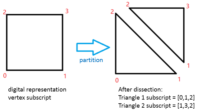
The data we send to the GPU represents a triangle, not a quadrilateral. A quadrilateral needs to be divided into two triangles and then passed to the GPU.
Based on four vertex data, the description information of the triangle is stored separately in the IndiceBuffer (that is, renderData.iDatas), and each value in IndiceBuffer represents the subscript of its corresponding vertex data. The index can merge the same vertex data in multiple triangles, reducing the total data size.
Source code
initQuadIndices(indices) {

    // The subscript obtained according to the above division method: [0,1,2] [1,3,2]

    // A group of 6 (corresponding to 1 quadrilateral) to generate index data

    let count = indices.length / 6;

    for (let i = 0, idx = 0; i < count; i++) {

        let vertextID = i * 4;

        indices[idx++] = vertextID;

        indices[idx++] = vertextID+1;

        indices[idx++] = vertextID+2;

        indices[idx++] = vertextID+1;

        indices[idx++] = vertextID+3;

        indices[idx++] = vertextID+2;
    }
}
Vertex Format Customization
Based on the interpretation of assembler and related classes above, there are several things to do for vertex format customization.
-
Define a new format
-
Prepare a long enough renderData with the new format
-
Write custom data in the corresponding position of renderData
-
In the
fillBuffers()method, therenderDatadata is correctly flushed into the buffer
// Customize the vertex format, add gfx.ATTR_UV1 on the basis of vfmtPosUvColor, remove gfx.ATTR_COLOR

    let gfx = cc.gfx;

    var vfmtCustom = new gfx.VertexFormat([

        { name: gfx.ATTR_POSITION, type: gfx.ATTR_TYPE_FLOAT32, num: 2 },

        { name: gfx.ATTR_UV0, type: gfx.ATTR_TYPE_FLOAT32, num: 2 }, // texture uv

        { name: gfx.ATTR_UV1, type: gfx.ATTR_TYPE_FLOAT32, num: 2 } // Custom data

    ]);

    const VEC2_ZERO = cc.Vec2.ZERO;

    export default class MovingBGAssembler extends GTSimpleSpriteAssembler2D {

    // Adjust the following constants according to the custom vertex format

    verticesCount = 4;

    indicesCount = 6;

    uvOffset = 2;

    uv1Offset = 4;

    floatsPerVert = 6;

    // Custom data will be written to the location of uv1

    public moveSpeed: cc.Vec2 = VEC2_ZERO;

    initData() {

        let data = this._renderData;

        // createFlexData supports the creation of renderData in the specified format

        data.createFlexData(0, this.verticesCount, this.indicesCount, this.getVfmt());

        // createFlexData will not fill in vertex index information, please add it manually

        let indices = data.iDatas[0];

        let count = indices.length / 6;

        for (let i = 0, idx = 0; i < count; i++) {

            let vert extID = i * 4;

            indices[idx++] = vertextID;

            indices[idx++] = vertextID+1;

            indices[idx++] = vertextID+2;

            indices[idx++] = vertextID+1;

            indices[idx++] = vertextID+3;

            indices[idx++] = vertextID+2;

        }
    }

    // The custom format is provided in the getVfmt() method, except for the current assembler, it will also be used in other places in render-flow

    getVfmt() {

        return vfmtCustom;

    }

    // Overload getBuffer(), return a buffer that can hold custom vertex data

    // The default fillBuffers() method will be called

    getBuffer() {

    return cc.renderer._handle.getBuffer(“mesh”, this.getVfmt());

    }

    // pos data has not changed, no need to reload

    // updateVerts(sprite) {//}

    updateUVs(sprite) {

        // uv0 calls the base class method to write

        super.updateUVs(sprite){

        // Fill in your own uv1 data

        // …

        // The method is similar to uv0 writing, see Demo for details

        // https://github.com/caogtaa/CCBatchingTricks

    }

    updateColor(sprite) {

        // Since the color field has been removed, the original method is overloaded here, and nothing is done

    }
}
Most of the GTSimpleSpriteAssembler2D base class code used above refers to the official cc.Sprite implementation.
Double UV Coordinate Shader Case
An additional set of uv data will be used to control the direction & speed of texture scrolling.
The method of using material parameters can also achieve this effect, but cannot achieve batch rendering.
Based on the Assembler class given above, continue to improve other auxiliary classes.
Material
Material is only used to associate effects, there is no additional logic, and no need to create uniform variables.
RenderComponent
The assembler can be understood as the rendering data assembler of the rendering component. The rendering component needs to be associated with the corresponding assembler to update and submit the rendering data. This example is based on the conventional cc.Sprite component and adds custom data moveSpeed to control texture movement.
@ccclass

export default class MovingBGSprite extends cc.Sprite {

    @property(cc.Vec2)

    moveSpeed: cc.Vec2 = cc.Vec2.ZERO;

// Pass the custom data to the assembler, call it after setting all parameters

// You can also actively pass the value in the moveSpeed setter method, you need to call setVertsDirty() to recalculate the vertex data

public FlushProperties() {

    let assembler: MovingBGAssembler = this._assembler;

    if (!assembler)

        return;

    assembler.moveSpeed = this.moveSpeed;

    this.setVertsDirty();

}

_resetAssembler () {

    this.setVertsDirty();

    let assembler = this._assembler = new MovingBGAssembler();

    this.FlushProperties();

    assembler.init(this);}

}
Effect (shader)
The scrolling effect is straightforward. Only the fragment shader code is posted here. The texture scrolling controls the direction and speed through v_uv1.xy.
CCProgram fs %{

    precision highp float;

    #include <cc-global>

    #include <cc-local>

    in vec2 v_uv0;

    in vec2 v_uv1;

    uniform sampler2D texture;

    void main()

    {

        vec2 uv = v_uv0.xy;

        float tx = cc_time.x * v_uv1.x;

        float ty = cc_time.x * v_uv1.y;

        uv.x = fract(uv.x - tx);

        uv.y = fract(uv.y + ty);

        vec4 col = texture(texture, uv);

        gl_FragColor = col;

    }

}%
Attach the RenderComponent to the corresponding node and assign the above materials to use.
At this point, a simple custom vertex format to achieve the purpose of batching is taking shape!
Demo example
The demo is based on Cocos Creator 2.4.0 and can be downloaded from GitHub
Conclusion
In actual projects, the custom vertex format can be used flexibly to achieve the purpose of passing parameters to the shader without interrupting the batching.
if you want to achieve batch rendering, there are other prerequisites to be met, including hierarchical node relationship, combined graph, texture state, etc.