
Cocos Creator implements various Shader effects based on SDF
Introduction
Developer muzzik shares his understanding of SDF with us and uses SDF to skillfully achieve effects such as shadows, strokes, and outer glow.
The full name of SDF is Signed Distance Field, which represents the distance from each point in space to the surface of the object.
• Signed: Refers to positive and negative numbers. Positive numbers represent outside the object, and negative numbers represent inside the object.
• Distance field: The value in it represents the distance to the object’s surface, and 0 represents the object’s surface. For example, a value of 5 means that the current point is outside the object, and there is still a distance of 5 from the surface, and a negative number is the opposite.
SDF is often used in font rendering, Ray Marching, physics engines, and other fields. Today we will implement some Shader effects based on SDF, including deformation animation, stroke, outer glow, shadow, etc.
Pre-knowledge
To facilitate those without a shader foundation of knowledge, here is a brief introduction to the basic understanding of shader; at the same time, the GLSL built-in functions used in this article are explained.
A shader is actually a GLSL (OpenGL Shading Language) program, and WebGL is an OpenGL packaged for the convenience of browsers.
Composition:
• Vertex shader: The model is composed of triangular faces, and the triangular faces are composed of vertices, and the vertex shader is responsible for the coordinate control of the vertices, which can be used to implement cloth, water, and so on.
• Fragment Shader: The fragment shader is responsible for the color output of the render position.
Description of the GLSL built-in functions used in this article:
• clamp(x, y, z): x < y returns y, x > z returns z, otherwise returns x
• mix(x, y, z): Linear aliasing of x, y, x(1 - z) + y * z
• length(x): Returns the modulo (length) of a vector, ie. sqrt(dot(x,x))
• sign(x): -1 if x < 0, 0 if x == 0, 1 if x > 0
Deformation animation
Draw a circle
If we want to draw a circle with SDF inside the Shader, how should we do it? It is simple. The code is as follows.
-
The parameter p is the position of the current rendering point because it is 2D graphics, so only x,y.
-
The parameter r is the radius of the circle we want to draw.
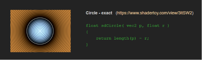
The returned result here is the distance field.
For example, the radius of the circle is 5. The circle is at 0,0 (all formulas are based on 0,0), the rendering point is at 0,3, then length ( p ) = 3, 3 - 5 = -2, then We have a distance of 2 from the surface of the circle, a negative number means the rendered point is inside the object.
Then all we have to do is “draw” it in the fragment shader:
-
output_v4: The color of the fragment shader output
-
float dist_f: distance field
-
vec4 color_v4: object color
output_v4 = mix(output_v4, color_v4, clamp(-dist_f, 0.0, 1.0));
- dist_f: Negative is positive, so inside the object clamp results in a valid value, outside the object is a negative number (clamp results in 0), the final result is the original output_v4, so only items inside the object mix will be effective.
Note: Below, I refer to the SDF value as the distance field. More SDF graphics formulas and principles are attached at the end of the article, and interested friends can continue to learn more.
Pan

I mentioned how to draw SDF graphics, so how to make them move? It’s straightforward. We only need to subtract the coordinates we want to move from the rendering point, pass the result point into the SDF function to obtain the distance field, and then get the moved distance field.
vec2 translate(vec2 render_v2_, vec2 move_v2_) {
return render_v2_ - move_v2_;
}
for example:
float dist_f = sdf_circle(translate(render_v2_, vec2(100.0, 100.0)), 10.0);
dist_f is the distance field after obtaining the translation vec2(100.0, 100.0) through the SDF function.
Rotate

Rotation is actually quite simple. Developers who have studied matrices should know that there is a rotation matrix. We only need to convert the vector * two-dimensional rotation matrix to get the rotated point:
// Counterclockwise rotation
vec2 rotate_ccw(vec2 render_v2_, float radian_f_) {
mat2 m = mat2(cos(radian_f_), sin(radian_f_), -sin(radian_f_), cos(radian_f_));
return render_v2_ * m;
}

// Clockwise rotation
vec2 rotate_cw(vec2 render_v2_, float radian_f_) {
mat2 m = mat2(cos(radian_f_), -sin(radian_f_), sin(radian_f_), cos(radian_f_));
return render_v2_ * m;
}
Display multiple objects
Note: Residual pixels are related to screen recording software
If you want to display multiple SDF objects normally, you only need to return the one with the smallest distance field of the two. One min is drafted:
float merge(float dist_f_, float dist2_f_) {
return min(dist_f_, dist2_f_);
}
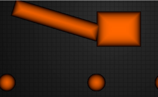
These effects are simple! By manipulating the distance field, we can get more effects. Please see below.
Intersect

Isn’t the effect weird? This function will only return < 0 when the distance fields of the two objects are < 0 at the same time. The method is also straightforward:
float intersect(float dist_f_, float dist2_f_) {
 // dist_f_ < 0, dist2_f_ > 0  Example dist_f_ = -2, dist2_f_ = 3,r = 3, Example dist_f_ = -2, dist2_f_ = 1,r = 1, then the value is > 0
 // dist_f_ > 0, dist2_f_ < 0 Example dist_f_ = 2, dist2_f_ = -1, r = 2, Example dist_f_ = 2, dist2_f_ = -5, r = 2, then the value is > 0
// dist_f_ > 0, dist2_f_ > 0 Example dist_f_ = 1, dist2_f_ = 2, r = 2, Example dist_f_ = 2, dist2_f_ = 1, r = 2, then the value is > 0
// dist_f_ < 0, dist2_f_ < 0 Example dist_f_ = -2, dist2_f_ = -3, r = -2, Example dist_f_ = -2, dist2_f_ = -1, r = -1, then the value is < 0
// So the final result will only be shown when dist_f_ and dist2_f_ coincide
 return max(dist_f_, dist2_f_);
}
The principle is that max will return a negative number only when two numbers are < 0 at the same time, so the above effect is caused.
Fusion

This effect is relatively common, and the implementation is as follows:
float smooth_merge(float dist_f_, float dist2_f_, float k_f_) {
 // k_f_ is invalid (0 or 1) if it does not exceed abs(dist_f_ - dist2_f_)
    float h_f = clamp(0.5 + 0.5 * (dist2_f_ - dist_f_) / k_f_, 0.0, 1.0);
 // Suppose k_f_ = 0, dist_f_ = 2, dist2_f_ = 1, then h_f = 0, mix(...) = dist2_f_, k_f_ * h_f * (1.0 - h_f) = 0 then the result is dist2_f_
 // Suppose k_f_ = 0, dist_f_ = 1, dist2_f_ = 2, then h_f = 1, mix(...) = dist_f_, k_f_ * h_f * (1.0 - h_f) = 0 then the result is dist_f_
 // If k_f_ is invalid, then the result will be = min(dist_f_, dist2_f_), the same as the merge result
 // if k_f_ is valid, then the result will be smaller than min(dist_f_, dist2_f_), the larger the k_f_, the smaller the result
    return mix(dist2_f_, dist_f_, h_f) - k_f_ * h_f * (1.0 - h_f);
}
As can be seen from the above, the result will only be operated when k_f_ > abs(dist_f_ - dist2_f_). If the incoming dist_f_ and dist2_f_ results are not much different, then it will be less than k_f_, so that the middle position of the two objects’ returned value is larger.
Offset

The overlapping part of the two during the movement disappears, and this is the offset effect:
float merge_exclude(float dist_f_, float dist2_f_) {
 // if dist_f_ < 0, dist2_f_ > 0 Example dist_f_ = -2 dist2_f_ = 6, r = -2, Example dist_f_ = -2 dist2_f_ = 3, r = -2
 // if dist_f_ > 0, dist2_f_ < 0 Example dist_f_ = 2 dist2_f_ = -6, r = -6, Example dist_f_ = -2 dist2_f_ = 3, r = -2
 // if dist_f_ > 0, dist2_f_ > 0 Example dist_f_ = 2 dist2_f_ = 6, r = 2, Example dist_f_ = 5 dist2_f_ = 3, r = 3
 // if dist_f_ < 0, dist2_f_ < 0 Example dist_f_ = -2 dist2_f_ = -3, r = 4, Example dist_f_ = -3 dist2_f_ = -2, r = 4
 // so the final result will only turn dist_f_ < 0 && dist2_f_ < 0 into > 0
 return min(max(-dist_f_, dist2_f_), max(-dist2_f_, dist_f_));
The ultimate purpose is to change the value of dist_f_ < 0 && dist2_f_ < 0 to a value > 0 so that it will get a positive number outside the object to achieve the offset effect.
Minus

The effect of “subtracting” is the same as the literal meaning, subtracting the overlapping part of another object, of course, the subtracted object will not be displayed, otherwise it will become an offset effect:
float substract(float dist_f_, float dist2_f_) {
 // dist_f_ < 0, dist2_f_ > 0 Example dist_f_ = -2, dist2_f_ = 3, r = 3, Example dist_f_ = -2, dist2_f_ = 1, r = 2, then value > 0
 // dist_f_ > 0, dist2_f_ < 0 Example dist_f_ = 2, dist2_f_ = -1, r = -1, Example dist_f_ = 2, dist2_f_ = -5, r = -2, then value < 0
 // dist_f_ > 0, dist2_f_ > 0 Example dist_f_ = 1, dist2_f_ = 2, r = 2, Example dist_f_ = 2, dist2_f_ = 1, r = 1, then value > 0
 // dist_f_ < 0, dist2_f_ < 0 Example dist_f_ = -2, dist2_f_ = -3, r = 4, Example dist_f_ = -2, dist2_f_ = -1, r = 4, then value > 0
 // so the final result will only show dist2_f_, and not when dist_f_ and dist2_f_ coincide
return max(-dist_f_, dist2_f_);
From the above example, it can be seen that only dist_f_ > 0 && dist2_f_ < 0 returns the value < 0, while other conditions result > 0.
-
dist_f_ > 0, dist2_f_ < 0 return < 0 means the rendering point is not in the first object and is displayed in the second object
-
And dist_f_ > 0, dist2_f_ < 0 returns > 0, which means that the rendering point is in two objects at the same time, that is, the offset effect
Stroke
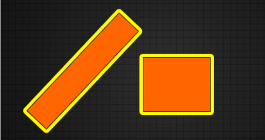
In addition to achieving different display effects through distance fields, we can also use distance fields for blending to achieve object strokes. Just one line of code to do it:
- output_v4: The color of the fragment shader output
- float dist_f: distance field
- vec4 color_v4: stroke color
- float width_f: stroke width
output_v4 = mix(output_v4, color_v4, abs(clamp(dist_f - width_f, 0.0, 1.0) - clamp(dist_f, 0.0, 1.0)));
It can be seen from the above code that the valid value of dist_f is (0~ 1.0 + width_ f), so it will return a negative number through clamp - clamp in this range, abs will convert it to a positive number, and then mix it through mix, then Gets the blended color of the edges of the object.
Inside/Outside Glow
Outer glow
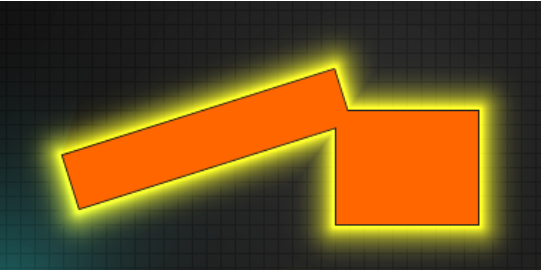
Radiate with power or radiation poisoning with this effect:
- float dist_f: distance field
- vec4 color_v4_: the color of the rendered point
- vec4 input_color_v4_: Outer glow color
- float radius_f_: outer glow radius
vec4 outer_glow(float dist_f_, vec4 color_v4_, vec4 input_color_v4_, float radius_f_) {
    // dist_f_ > radius_f_ results in 0
    // dist_f_ < 0 results in 1
    // dist_f_ > 0 && dist_f_ < radius_f_ then the larger the dist_f_ the smaller the a_f, range 0 ~ 1
    float a_f = abs( clamp(dist_f_ / radius_f_, 0.0, 1.0) - 1.0);
    // pow: smoothing a_f
    // max and min: prevent rendering inside the object
    float b_f = min(max(0.0, dist_f_), pow(a_f, 5.0)).
    Returns color_v4_ + input_color_v4_ * b_f;
}
The range of valid values for dist_f_ is ( 0 ~ radius ).
-
If dist_f_ > radius_f_:
a_f = 0;
b_f = min(max(0.0, dist_f_), 0) = 0;
The return value is color_v4_, which is invalid at this time. -
If dist_f_ < 0:
a_f = 1;
b_f = min(max(0.0, dist_f_), 1) = 0;
The return value is color_v4_, which is invalid at this time.
Inner glow
The creation of the inner glow effect is rewritten according to the above outer glow:
vec4 inner_glow(float dist_f_, vec4 color_v4_, vec4 input_color_v4_, float radius_f_) {
    // (dist_f_ + radius_f_) > radius_f_ results in 1
    // (dist_f_ + radius_f_) < 0 Result is 0
    // (dist_f_ + radius_f_) > 0 && (dist_f_ + radius_f_) < radius_f_ then the larger the dist_f_ the larger the a_f, range 0 ~ 1
    float a_f = clamp((dist_f_ + radius_f_) / radius_f_, 0.0, 1.0);
    // pow: smoothing a_f
    // 1.0+: render inside the object
    // max(1.0, sign(dist_f_) * -: returns -1 if dist_f_ < 0, 0 if dist_f_ == 0, 1 if dist_f_ > 0, so valid values are inside the object only
    float b_f = 1.0 - max(1.0, sign(dist_f_) * -(1.0 + pow(a_f, 5.0)));
  return color_v4_ + input_color_v4_ * b_f;
}
- If (dist_f_ + radius_f_) > radius_f_ :
a_f = 1.0;
b_f = 1.0 - max(1.0, -2.0) = 0;
The return value is color_v4_, which is invalid at this time.
- If (dist_f_ + radius_f_) < 0:
a_f = 0.0;
b_f = 1.0 - max(1.0, 1.0) = 0;
The return value is color_v4_, which is invalid at this time.
Since dist_f gets smaller as it goes inside the object, it also causes a_f to do the same, so the last 1.0 - max.
Shadow
Hard shadow
Note: Residual pixels are related to screen recording software
What are hard shadows? Shadows without transitions around the edges are hard shadows. Our SDF can not only generate all kinds of graphics at the same time but also do shadows!
The implementation principle of hard shadows is: from the rendering point to the light source point, step in turn the safe distance (SDF distance field, representing this range will not touch the object), if the distance field < 0, it means that the object is touched, return 0, and then the color *= return value of our light source, we get the shadow.
Go directly to the code:
- vec2 render_v2_ render point
- vec2 light_v2_ light point
float shadow(vec2 render_v2_, vec2 light_v2_) {
  // the direction vector from the current render position to the light source position
    vec2 render_to_light_dir_v2 = normalize(light_v2_ - render_v2_);
  // distance from rendering position to light source position
    float render_to_light_dist_f = length(render_v2_ - light_v2_);
  // travel distance
    float travel_dist_f = 0.01;
    for (int k_i = 0; k_i < max_shadow_step; ++k_i) {
      // distance from rendering point to scene
      float dist_f = scene_dist(render_v2_ + render_to_light_dir_v2 * travel_dist_f);
      // Less than 0 means inside the object
      if (dist_f < 0.0) {
        return 0.0;
      }

      // abs: avoid going backwards
      // max avoid rendering points too close to the physical surface resulting in a very small exhaustion of traversals, so it is possible to skip drawing shadows where the object distance is less than 1.0

      travel_dist_f += max(1.0, abs(dist_f));

      // travel_dist_f += abs(dist_f); exact shadows
      // Render point distance over light source point

      if (travel_dist_f > render_to_light_dist_f) {
        return 1.0;
      }
    }
    return 0.0;
  }
Soft shadow
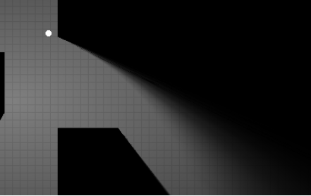
figure 1
figure 2
Soft shadows are more realistic than hard shadows. There are two kinds of soft shadows in SDF that I understand currently. One is the formula mentioned in iq and games202, but the effect is not good. When it is close to the object, it will produce soft curved shadows (picture 1 above); This article will refer to the code of another great developer on Shadertoy, and the effect is very good (picture 2 above).
Code first:
float shadow(vec2 render_v2_, vec2 light_v2_, float hard_f_) {
  // the direction vector from the current render position to the light source position
  vec2 render_to_light_dir_v2 = normalize(light_v2_ - render_v2_);
  // distance from rendering position to light source position
  float render_to_light_dist_f = length(render_v2_ - light_v2_);
  // part of the visible light, starting from a radius (the lower half is added last).
  float brightness_f = hard_f_ * render_to_light_dist_f;
  // distance traveled
  float travel_dist_f = 0.01;
  for (int k_i = 0; k_i < max_shadow_step; ++k_i) {
  // distance from the current position to the scene
  float dist_f = scene_dist(render_v2_ + render_to_light_dir_v2 * travel_dist_f);
  // render point inside the object
  if (dist_f < -hard_f_) {
   return 0.0;
  }

  // dist_f stays the same, the smaller the brightness_f, the smaller the brightness_f as it gets closer to the light source and object
  brightness_f = min(brightness_f, dist_f / travel_dist_f);

  // max avoids rendering points too close to the physical surface resulting in a very small exhaustion of traversal times, so it is possible to skip shadows drawn with object distances less than 1.0
  // abs Avoid going backwards

  travel_dist_f += max(1.0, abs(dist_f));

  // render points at distances greater than the light source point

  if (travel_dist_f > render_to_light_dist_f) {
   break;
  }
 }

 // brightness_f * render_to_light_dist_f is smoothed according to distance, the closer to the light source the smaller the result, eliminating ripple lines
 // zoom in on the shadow, the larger the hard_f the smaller the result, the larger the shadow, hard_f_ / (2.0 * hard_f_) makes the result close to 0.5, used to smooth the transition

 brightness_f = clamp((brightness_f * render_to_light_dist_f + hard_f_) / (2.0 * hard_f_), 0.0, 1.0);
 brightness_f = smoothstep(0.0, 1.0, brightness_f);
 return brightness_f;
}
The principle of this implementation is: from the rendering point to the light source point, step by step, the safe distance (SDF distance field, which means that this range will not touch the object), if the distance field < -hard_f_ returns 0, why is -hard_f_, because we want to draw the shadow with a hard_f_ distance from the surface of the object so that the soft shadow can transition into the range of the hard shadow and look more realistic.
The Demo of this article is placed in the Gitee repository:
We have excellent reference links to help you if you want to learn more.
References
More SDF graph formulas
Explanation of the principle of graphic formulas
https://blog.csdn.net/qq_41368247/article/details/106194092
shadertoy 2D soft shadow implementation
Soft shadows and hard shadows