
Our reletive expert in 3D Shading, Kylins, has come back to share their take on how to improve the look of water in Cocos Creator.
1. Opening
Since the last time I wrote “Enhancing the Image Value with Real-time Reflection Shader,” many developers have begun to use it to render water surfaces, but the results are not satisfactory. This is because there are many details to consider in addition to reflections on the water surface.
Before this, many developers mentioned the need for water surface rendering, with many developers sharing some shaders simulating water surface rendering but more focused on the direction of cartoon coloring.
The demand for water surface rendering in 3D projects is enormous. After all, the water surface of the earth’s surface accounts for about 70.8%, and it is difficult to avoid the water surface effect.
Recently, youyou from the engine team has also created a water surface rendering effect in “Lake,” including many real-time rendering technologies such as plane reflection, FSR, SSAO, TAA, etc.
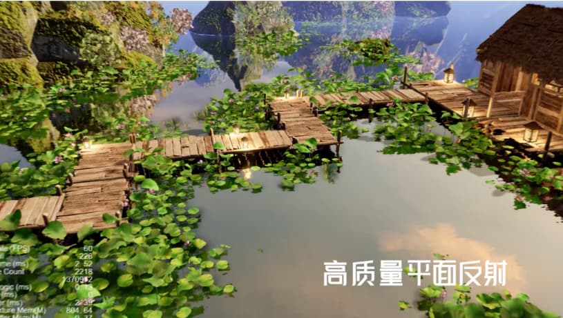
However, this project is based on Cocos Creator’s deferred rendering pipeline, which has high requirements for the project and your device. I’ve specially prepared this independent water surface effect to share and hope to help everyone understand it.
2. Water surface rendering process
There are many water surface rendering technologies, and products of different tiers have different requirements for the water surface.
In the article “Summary of Realistic Water Rendering Technology” by Mao Xingyun, through the analysis of water surface rendering of some AAA masterpieces. Water surface rendering techniques are sorted from simple to complex and can be divided into the following three categories:
- Flat Shading
- Vertex animation
- Fluid simulation
This article implements a water surface effect based on plane shading; although it is not a high-end effect, it is the solution used in most 3D projects.
Water surface rendering based on plane shading mainly involves the following parts:
- reflection
- refraction
- water depth effect
- soft edge
- Dynamic Skybox
Normal Map and LightingShore waves
Due to time constraints, the normal map, lighting, and shore waves have not yet been implemented.
The standard rendering process is as follows:
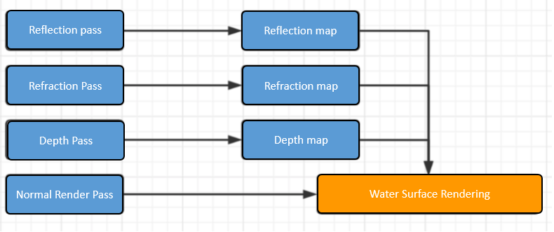
If you want to achieve all the effects, you need to draw the scene at least 4 times.
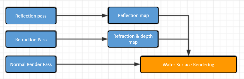
Since the depth map here is only used with refraction, 8-bit precision is enough, and we can consider borrowing the alpha channel in the refraction map to store depth information.
The optimized flow chart is as follows:
3. Reflection map rendering
I’ve completely analyzed the principles of real-time reflection in “Enhancing the Image Value with Real-time Reflection Shader,” so I won’t describe it here. Readers who need to know can click here to view it directly.
Here we mainly talk about the implementation steps in this DEMO.
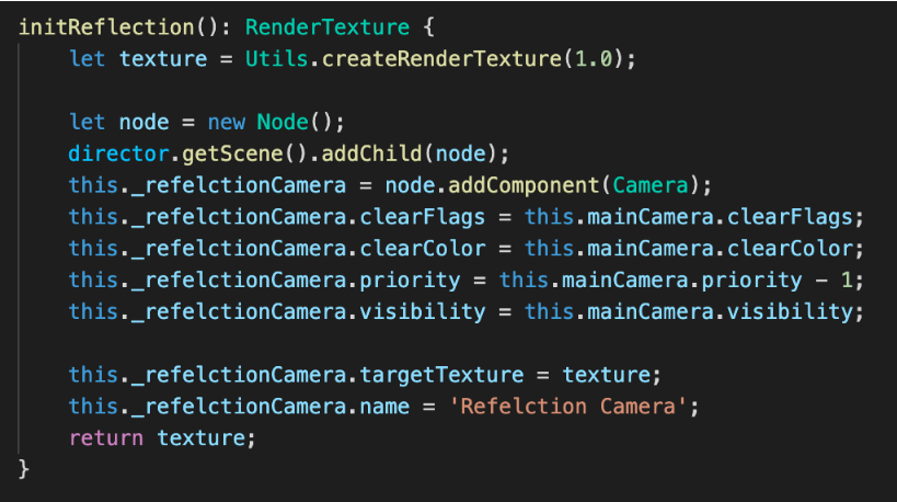
Step 1: Create a new RenderTexture using code.
Step 2: Create a node, add the camera component, and synchronize the clearFlags, clearColor, and visibility properties with the main camera.
Step 3: Set the rendering priority of the reflection camera, making sure to render before the main camera.
Step 4: Assign the newly created RenderTexture to the targetTexture property of this camera.
The code for the above steps is in WaterPlane.ts, as shown in the following figure:
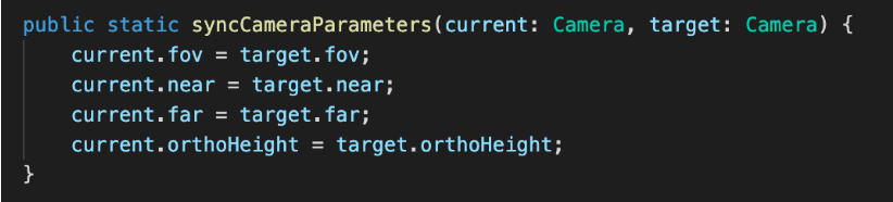
Step 5: Synchronize main camera parameters in lateUpdate.
Step 6: In lateUpdate, according to the principle of real-time reflection, dynamically calculate the mirror position and rotation of the camera about the main camera.
Finally, the rendered RenderTexture is as follows:
Kylin Tips:
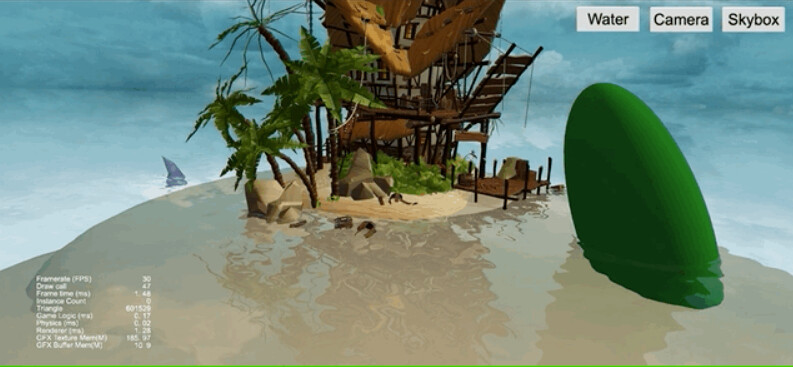
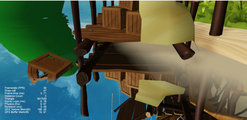
For the materials of all objects, you need to add a custom clipping plane to cut out the part below the water surface. You can clearly see that the reflection of the green object in the above picture, the part below the water surface, is cropped.
4. Refraction map rendering
The principle of refraction rendering is straightforward:
-
Render the part below the horizontal plane to RenderTexture.
-
The noise map is scrambled during the water rendering stage to simulate a refraction effect on the water surface.
The process of refraction rendering is roughly the same as reflection rendering, with only two minor differences:
-
All camera parameters used for refraction rendering should be consistent with the main camera.
-
In the refraction rendering stage, the part above the water surface is cropped out of the object
Let’s take a look at the implementation steps of refraction.
Step 1: Create a new RenderTexture using code.
Step 2: Create a node, add the camera component, and synchronize the** clearFlags, clearColor**, and visibility properties with the main camera.
Step 3: Set the rendering priority of the reflection camera, making sure to render before the main camera.
Step 4: Assign the newly created RenderTexture to the targetTexture property of this camera.
The code for the above steps is in WaterPlane.ts, as shown in the following figure:
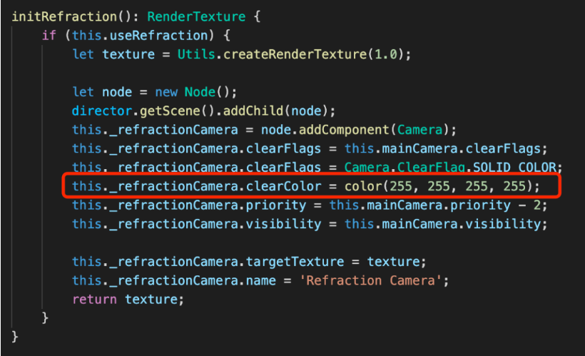
Kylin Tips: Pay attention to the red wireframe part, the Alpha channel of the refraction map in this DEMO is used to mark the depth information, so you need to ensure that the value of the Alpha channel is 255.
Step 5: Synchronize the main camera parameters, position, rotation, and other information in lateUpdate.
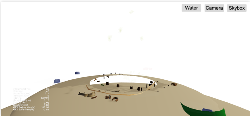
Finally, the rendered RenderTexture is as follows:
5. Water surface rendering
Water surface rendering mainly uses projection texture technology, converting vertices’ projection coordinates into UV, and samples refraction and reflection maps.
Due to using a refraction map, our water surface material does not need to have alpha blending turned on.
Refraction rendering
Step 1: Calculate the screen UV according to the projected coordinates. As follows:
vec2 screenUV = v_screenPos.xy / v_screenPos.w * 0.5 + 0.5;
Step 2: Sampling the refraction map, you can get the following rendering effect:
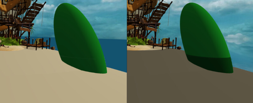
The left is the normal rendering effect, and the right is the effect of marking the refraction content
Step 3: Use the noise map to perturb the refraction to get the following effects:
Reflection rendering
Step 1: As with refraction rendering, the screen UV is calculated based on the projected coordinates.
Step 2: Sampling the reflection map, you can get the following rendering effect:
Step 3: Use the noise map to perturb the reflection to get the following effects:
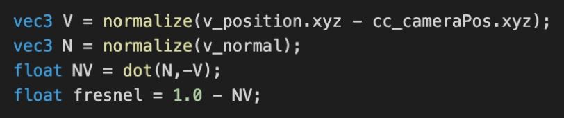
Fresnel mix
Fresnel’s calculation formula has appeared many times, from Yutu’s edge light tutorial to real-time reflection and other occasions. Here is the core code:
Refraction can be regarded as the natural color of the water body. By mixing the Fresnel factor with the reflection content, a water body effect with refraction and reflection can be achieved.
The pseudo code is as follows:
finalColor = mix(refractionColor,reflectionColor,fresnel)
Finally, the following display effect can be obtained:
Please check the effect-water.effect file in the project for the complete code.
6. Water depth effect
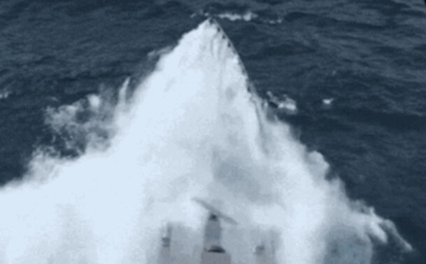
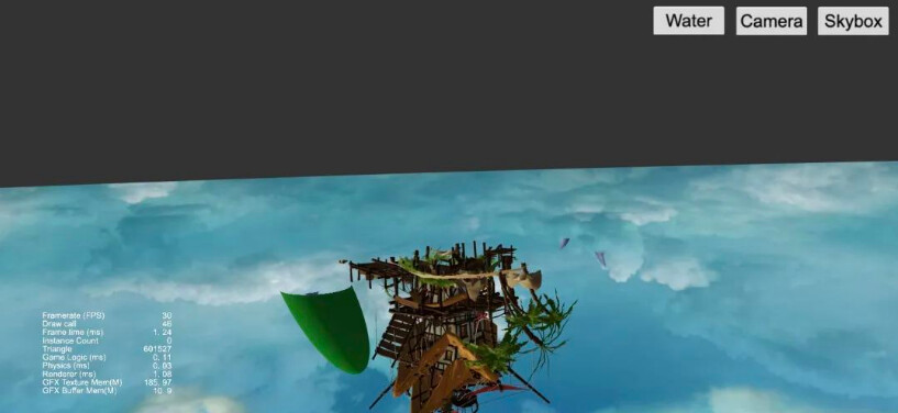
As you can see from the animation above, although the refraction and reflection effects are there, the painting style is a bit strange. There is no feeling of water surface at all.
This is caused by the lack of depth effect on the water surface.
Let’s take a look at how to obtain depth information and realize the water depth effect according to the depth information.
Get in-depth information
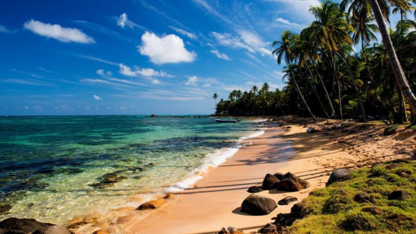
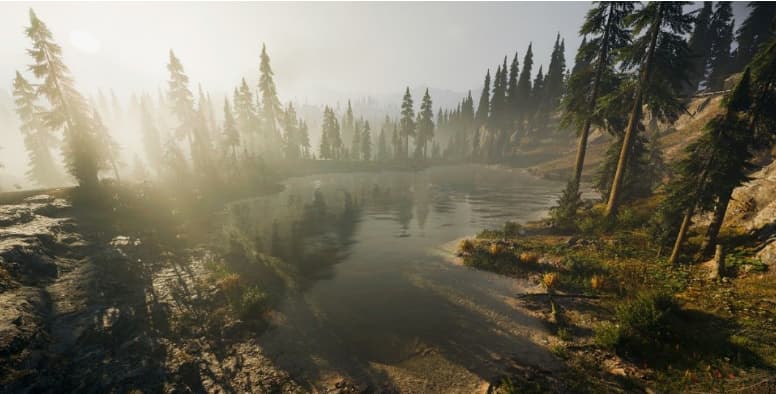
From the image above, we can clearly see that the color of the water near the shore is much more transparent than the color of the water farther away.
The main reason for this phenomenon is that the thickness of the water body is different based on the line of sight.
What is the thickness of the water body based on the line of sight direction? Please see the following figure:
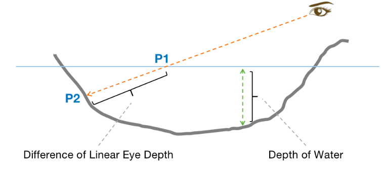
The depth of the water body we usually say refers to the height difference from the water surface to the bottom of the water, ignoring the line of sight factor.
Without going into the details, we can simply use the height difference as the depth of the water.
A possible pseudocode is as follows:
depth = clamp((g_waterLevel - v_position.y) * depthScale,0.0,1.0);
Where depthScale is our depth scaling factor, which can be used to adjust the scale problem and the linear decay rate of water visibility.
The thickness of the water body based on the sight direction refers to the distance difference between the sight direction and the intersection of the horizontal plane and the water bottom — the distance from point P1 to point P2 in the figure.
Let’s derive a formula that uses the thickness of the water body based on the sight direction as the depth factor.
The first reaction of many friends is to solve the equation of the line, but it is easier to solve it with the characteristics of the space vector.
For the convenience of comparison and understanding, view the above picture again:
Let the viewing direction be viewDir, and the thickness is depth:
P1 + viewDir * depth = P2
Split into component operations to get:
P1.x + viewDir.x * depth = P2.x
P1.y + viewDir.y * depth = P2.y
P1.z + viewDir.z * depth = P2.z
It can be deduced:
depth = (P2.y - P1.y) / viewDir.y
From this, the following calculation formula can be obtained:
vec3 viewDir = normalize(v_position.xyz - cc_cameraPos.xyz);
float depth = (v_position.y - g_waterLevel) / viewDir.y
depth = clamp(depth * depthScale,0.0,1.0);
Compared with using the depth of the water body directly, there is one more operation to find the unit vector of viewDir, and one more operation to divide by viewDir.y.
In non-extreme cases, this extra pure logic operation is negligible on the GPU and can be used with confidence.
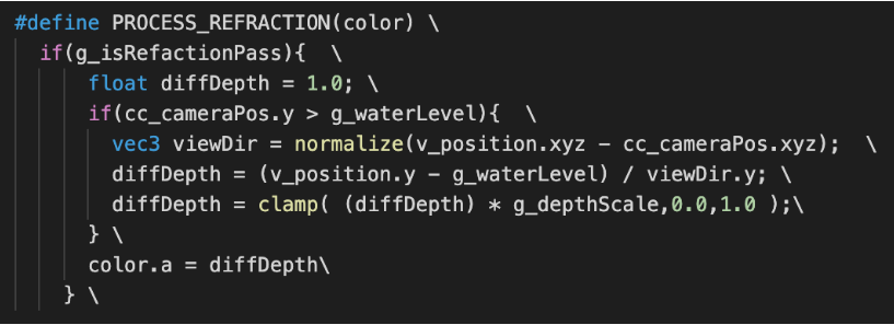
Add the above formula to the shader of the rendering object, enable it in the refraction rendering stage, and store the result in the alpha channel.
The Shader code in the project is shown in the following figure:
The final depth information is as follows:
Deep blend
With the above depth information, we only need to use the depth information to mix with the bottom color after calculating the refraction color. The Shader code is shown in the following figure:
IMAGE
Since the visibility of the water body is nonlinear, the pow function is used for diffDepth and the power parameter defaults to 2.0.
In the end, the following results can be obtained:
6. The soft edge of the water bank
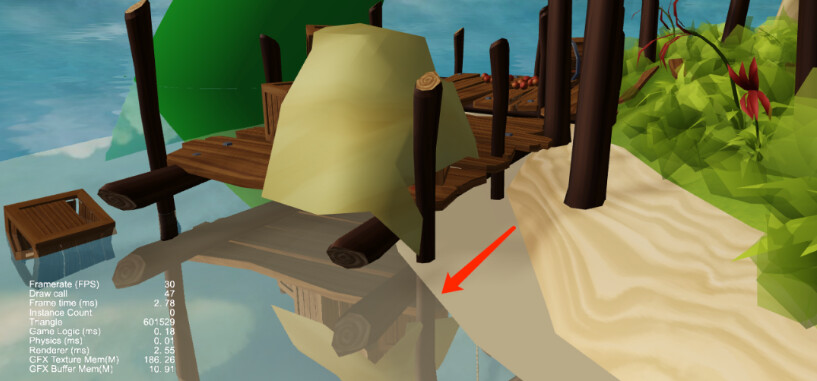
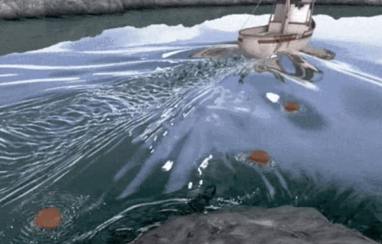
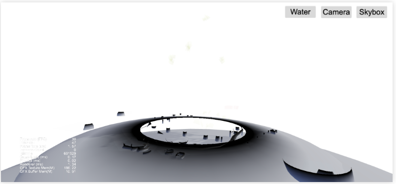
When we zoomed in on the camera and observed the intersection of the water surface and the object, we could see a clear boundary.
This boundary is more apparent when the reflection is stronger, which greatly reduces the effect of our water surface.
Fortunately, we already have the depth information, and we can judge where it is close to the shore according to the depth and modify the Fresnel factor so that the reflection is weaker as it is closer to the shore.
The core code is as follows:
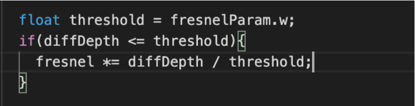
Finally, in the case of total reflection, the water surface and the shore can still smoothly transition. Results as shown below:
Here’s another picture from a distance perspective:
7. Dynamic skybox
A dynamic skybox is used to enhance the atmosphere in the DEMO.
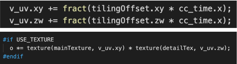
This is a straightforward and efficient dynamic skybox solution, which only uses a hemisphere model with two-layer texture mixing and adjusts the horizontal flow speed of the two textures.
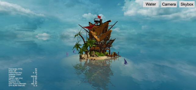
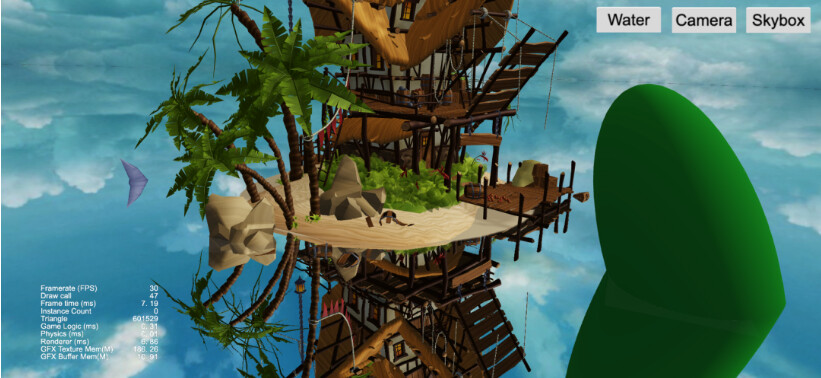
8. About DEMO
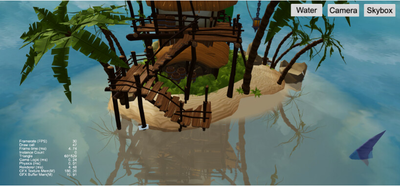
All effect parameters can be adjusted as shown below:
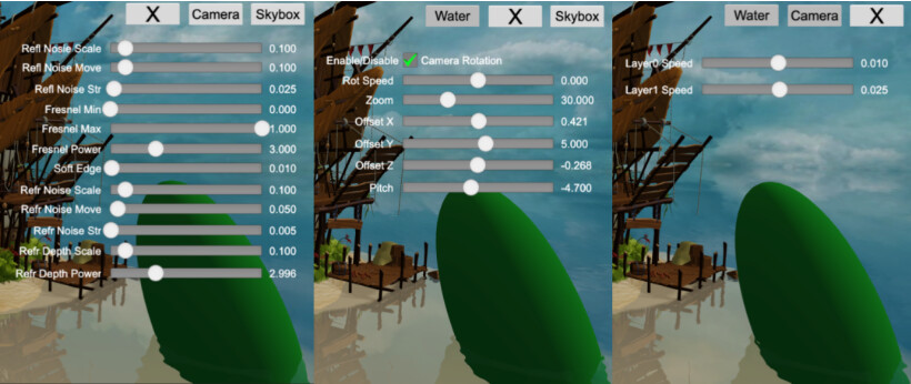
To download the DEMO, go to: Cocos Store